21 Jul 2020
This is an ongoing series of posts on ELF Binary Relocations and Thread
Local Storage. This article covers only Thread Local Storage and assumes
the reader has had a primer in ELF Relocations, if not please start with
my previous article ELF Binaries and Relocation Entries.
This is the third part in an illustrated 3 part series covering:
In the last article we covered how Thread Local Storage (TLS) works at runtime,
but how do we get there? How does the compiler and linker create the memory
structures and code fragments described in the previous article?
In this article we will discuss how TLS relocations are is implemented. Our
outline:
As before, the examples in this article can be found in my tls-examples
project. Please check it out.
I will assume here that most people understand what a compiler and assembler
basically do. In the sense that compiler will compile routines
written C code or something similar to assembly language. It is then up to the
assembler to turn that assembly code into machine code to run on a CPU.
That is a big part of what a toolchain does, and it’s pretty much that simple if
we have a single file of source code. But usually we don’t have a single file,
we have the multiple files, the c runtime,
crt0 and other libraries like
libc. These all need to be
put together into our final program, that is where the complexities of the
linker comes in.
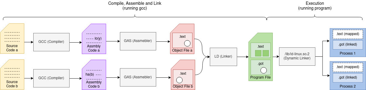
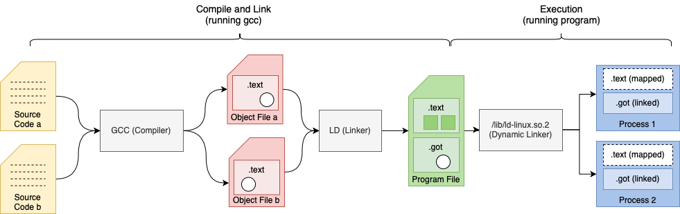
In this article I will cover how variables in our source code (symbols) traverse
the toolchain from code to the memory in our final running program. A picture that looks
something like this:
The Compiler
First we start off with how relocations are created and emitted in the compiler.
As I work primarily on the GNU toolchain with
it’s GCC compiler we will look at that, let’s get started.
GCC Legitimize Address
To start we define a symbol as named address in memory. This address can be
a program variable where data is stored or function reference to where a
subroutine starts.
In GCC we have have TARGET_LEGITIMIZE_ADDRESS, the OpenRISC implementation
being or1k_legitimize_address().
It takes a symbol (memory address) and makes it usable in our CPU by generating RTX
sequences that are possible on our CPU to load that address into a register.
RTX represents a tree node in GCC’s register transfer language (RTL). The RTL
Expression is used to express our algorithm as a series of register transfers.
This is used as register transfer is basically what a CPU does.
A snippet from legitimize_address() function is below. The argument x
represents our input symbol (memory address) that we need to make usable by our
CPU. This code uses GCC internal API’s to emit RTX code sequences.
static rtx
or1k_legitimize_address (rtx x, rtx /* unused */, machine_mode /* unused */)

    ...

	case TLS_MODEL_NONE:
	  t1 = can_create_pseudo_p () ? gen_reg_rtx (Pmode) : scratch;
	  if (!flag_pic)
	    {
	      emit_insn (gen_rtx_SET (t1, gen_rtx_HIGH (Pmode, x)));
	      return gen_rtx_LO_SUM (Pmode, t1, x);
	    }
	  else if (is_local)
	    {
	      crtl->uses_pic_offset_table = 1;
	      t2 = gen_sym_unspec (x, UNSPEC_GOTOFF);
	      emit_insn (gen_rtx_SET (t1, gen_rtx_HIGH (Pmode, t2)));
	      emit_insn (gen_add3_insn (t1, t1, pic_offset_table_rtx));
	      return gen_rtx_LO_SUM (Pmode, t1, copy_rtx (t2));
	    }
	  else
	    {
              ...
We can read the code snippet above as follows:
- This is for the non
TLS case as we see TLS_MODEL_NONE.
- We reserve a temporary register
t1.
- If not using Position-independent code (
flag_pic) we do:
- Emit an instruction to put the high bits of
x into our temporary register t1.
- Return the sum of
t1 and the low bits of x.
- Otherwise if the symbol is static (
is_local) we do:
- Mark the global state that this object file uses the
uses_pic_offset_table.
- We create a Global Offset Table offset variable
t2.
- Emit an instruction to put the high bits of
t2 (the GOT offset) into out temporary register t1.
- Emit an instruction to put the sum of
t1 (high bits of t2) and the GOT into t1`.
- Return the sum of
t1 and the low bits of t1.
You may have noticed that the local symbol still used the global offset
table (GOT). This is
because Position-idependent code requires using the GOT to reference symbols.
An example, from nontls.c:
static int x;

int *get_x_addr() {
   return &x;
}
Example of the non pic case above, when we look at the assembly code generated by GCC
we can see the following:
	.file	"nontls.c"
	.section	.text
	.local	x
	.comm	x,4,4
	.align 4
	.global	get_x_addr
	.type	get_x_addr, @function
get_x_addr:
	l.addi	r1, r1, -8       # \
	l.sw	0(r1), r2        # | function prologue
	l.addi	r2, r1, 8        # |
	l.sw	4(r1), r9        # /
	l.movhi	r17, ha(x)       # \__ legitimize address of x into r17
	l.addi	r17, r17, lo(x)  # /
	l.or	r11, r17, r17    # } place result in return register r11
	l.lwz	r2, 0(r1)        # \
	l.lwz	r9, 4(r1)        # | function epilogue
	l.addi	r1, r1, 8        # |
	l.jr	r9               # |
	 l.nop                   # /

	.size	get_x_addr, .-get_x_addr
	.ident	"GCC: (GNU) 9.0.1 20190409 (experimental)"
Example of the local pic case above the same code compiled with the -fPIC GCC option
looks like the following:
	.file	"nontls.c"
	.section	.text
	.local	x
	.comm	x,4,4
	.align 4
	.global	get_x_addr
	.type	get_x_addr, @function
get_x_addr:
	l.addi	r1, r1, -8      # \
	l.sw	0(r1), r2       # | function prologue
	l.addi	r2, r1, 8       # |
	l.sw	4(r1), r9       # /
	l.jal	8                                             # \
	 l.movhi	r19, gotpchi(_GLOBAL_OFFSET_TABLE_-4) # | PC relative, put
	l.ori	r19, r19, gotpclo(_GLOBAL_OFFSET_TABLE_+0)    # | GOT into r19
	l.add	r19, r19, r9                                  # /
	l.movhi	r17, gotoffha(x)        # \
	l.add	r17, r17, r19           # | legitimize address of x into r17
	l.addi	r17, r17, gotofflo(x)   # /
	l.or	r11, r17, r17   # } place result in return register r11
	l.lwz	r2, 0(r1)       # \
	l.lwz	r9, 4(r1)       # | function epilogue
	l.addi	r1, r1, 8       # |
	l.jr	r9              # |
	 l.nop                  # /

	.size	get_x_addr, .-get_x_addr
	.ident	"GCC: (GNU) 9.0.1 20190409 (experimental)"
TLS and Addend cases are also handled by or1k_legitimize_address().
GCC Print Operand
Once RTX is generated by legitimize address and GCC passes
run all of their optimizations the RTX needs to be printed out as assembly code. During
this process relocations are printed by GCC macros TARGET_PRINT_OPERAND_ADDRESS
and TARGET_PRINT_OPERAND. In OpenRISC these defined
by or1k_print_operand_address()
and or1k_print_operand().
Let us have a look at or1k_print_operand_address().
/* Worker for TARGET_PRINT_OPERAND_ADDRESS.
   Prints the argument ADDR, an address RTX, to the file FILE.  The output is
   formed as expected by the OpenRISC assembler.  Examples:
     RTX							      OUTPUT
     (reg:SI 3)							       0(r3)
     (plus:SI (reg:SI 3) (const_int 4))				     0x4(r3)
     (lo_sum:SI (reg:SI 3) (symbol_ref:SI ("x")))		   lo(x)(r3)  */

static void
or1k_print_operand_address (FILE *file, machine_mode, rtx addr)
{
  rtx offset;

  switch (GET_CODE (addr))
    {
    case REG:
      fputc ('0', file);
      break;
    case ...
    case LO_SUM:
      offset = XEXP (addr, 1);
      addr = XEXP (addr, 0);
      print_reloc (file, offset, 0, RKIND_LO);
      break;
    default: ...
    }

  fprintf (file, "(%s)", reg_names[REGNO (addr)]);
}
The above code snippet can be read as we explain below, but let’s first
make some notes:
- The input RTX
addr for TARGET_PRINT_OPERAND_ADDRESS will usually contain
a register and an offset typically this is used for LOAD and STORE
operations.
- Think of the RTX
addr as a node in an AST.
- The RTX node with code
REG and SYMBOL_REF are always leaf nodes.
With that, and if we use the or1k_print_operand_address() c comments above as examples
of some RTX addr input we will have:
    RTX     |    (reg:SI 3)          (lo_sum:SI (reg:SI 3) (symbol_ref:SI("x")))
 -----------+--------------------------------------------------------------------
    TREE    |
   (code)   |  (code:REG regno:3)                (code:LO_SUM)
   /    \   |                                      /        \
  (0)   (1) |                         (code:REG regno:3)  (code:SYMBOL_REF "x")
We can now read the above snippet as:
- First get the
CODE of the RTX.
- If
CODE is REG (a register) than our offset can be 0.
- If
IS is LO_SUM (an addition operation) then we need to break it down to:
- Arg
0 is our new addr RTX (which we assume is a register)
- Arg
1 is an offset (which we then print with print_reloc())
- Second print out the register name now in
addr i.e. “r3”.
The code of or1k_print_operand() is similar and the reader may be inclined to
read more details. With that we can move on to the assembler.
TLS cases are also handled inside of the print_reloc() function.
The Assembler
In the GNU Toolchain our assembler is GAS, part of binutils.
The code that handles relocations is found in the function
parse_reloc()
found in opcodes/or1k-asm.c. The function parse_reloc() is the direct counterpart of GCC’s print_reloc()
discussed above. This is actually part of or1k_cgen_parse_operand()
which is wired into our assembler generator CGEN used for parsing operands.
If we are parsing a relocation like the one from above lo(x) then we can
isolate the code that processes that relocation.
static const bfd_reloc_code_real_type or1k_imm16_relocs[][6] = {
  { BFD_RELOC_LO16,
    BFD_RELOC_OR1K_SLO16,
...
    BFD_RELOC_OR1K_TLS_LE_AHI16 },
};

static int
parse_reloc (const char **strp)
{
    const char *str = *strp;
    enum or1k_rclass cls = RCLASS_DIRECT;
    enum or1k_rtype typ;

    ...
    else if (strncasecmp (str, "lo(", 3) == 0)
      {
	str += 3;
	typ = RTYPE_LO;
      }
    ...

    *strp = str;
    return (cls << RCLASS_SHIFT) | typ;
}
This uses strncasecmp to match
our "lo(" string pattern. The returned result is a relocation type and relocation class
which are use to lookup the relocation BFD_RELOC_LO16 in the or1k_imm16_relocs[][] table
which is indexed by relocation class and relocation class.
The assembler will encode that into the ELF binary. For TLS relocations the exact same
pattern is used.
The Linker
In the GNU Toolchain our object linker is the GNU linker LD, also part of the
binutils project.
The GNU linker uses the framework
BFD or Binary File
Descriptor which
is a beast. It is not only used in the linker but also used in GDB, the GNU
Simulator and the objdump tool.
What makes this possible is a rather complex API.
BFD Linker API
The BFD API is a generic binary file access API. It has been designed to support multiple
file formats and architectures via an object oriented, polymorphic API all written in c. It supports file formats
including a.out,
COFF and
ELF as well as
unexpected file formats like
verilog hex memory dumps.
Here we will concentrate on the BFD ELF implementation.
The API definition is split across multiple files which include:
- bfd/bfd-in.h - top level generic APIs including
bfd_hash_table
- bfd/bfd-in2.h - top level binary file APIs including
bfd and asection
- include/bfdlink.h - generic bfd linker APIs including
bfd_link_info and bfd_link_hash_table
- bfd/elf-bfd.h - extensions to the APIs for ELF binaries including
elf_link_hash_table
bfd/elf{wordsize}-{architecture}.c - architecture specific implementations
For each architecture implementations are defined in bfd/elf{wordsize}-{architecture}.c. For
example for OpenRISC we have
bfd/elf32-or1k.c.
Throughout the linker code we see access to the BFD Linker and ELF APIs. Some key symbols to watch out for include:
info - A reference to bfd_link_info top level reference to all linker
state.htab - A pointer to elf_or1k_link_hash_table from or1k_elf_hash_table (info), a hash
table on steroids which stores generic link state and arch specific state, it’s also a hash
table of all global symbols by name, contains:
htab->root.splt - the output .plt sectionhtab->root.sgot - the output .got sectionhtab->root.srelgot - the output .relgot section (relocations against the got)htab->root.sgotplt - the output .gotplt sectionhtab->root.dynobj - a special bfd to which sections are added (created in or1k_elf_check_relocs)
sym_hashes - From elf_sym_hashes (abfd) a list of for global symbols
in a bfd indexed by the relocation index ELF32_R_SYM (rel->r_info).h - A pointer to a struct elf_link_hash_entry, represents link state
of a global symbol, contains:
h->got - A union of different attributes with different roles based on link phase.h->got.refcount - used during phase 1 to count the symbol .got section referencesh->got.offset - used during phase 2 to record the symbol .got section offseth->plt - A union with the same function as h->got but used for the .plt section.h->root.root.string - The symbol name
local_got- an array of unsigned long from elf_local_got_refcounts (ibfd) with the same
function to h->got but for local symbols, the function of the unsigned long is changed base
on the link phase. Ideally this should also be a union.tls_type - Retrieved by ((struct elf_or1k_link_hash_entry *) h)->tls_type used to store the
tls_type of a global symbol.local_tls_type - Retrieved by elf_or1k_local_tls_type(abfd) entry to store tls_type for local
symbols, when h is NULL.root - The struct field root is used in subclasses to represent the parent class, similar to how super is used
in other languages.
Putting it all together we have a diagram like the following:
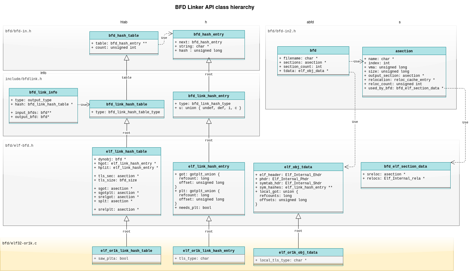
Now that we have a bit of understanding of the data structures
we can look to the link algorithm.
The link process in the GNU Linker can be thought of in phases.
Phase 1 - Book Keeping (check_relocs)
The or1k_elf_check_relocs() function is called during the first phase to
do book keeping on relocations. The function signature looks like:
static bfd_boolean
or1k_elf_check_relocs (bfd *abfd,
                       struct bfd_link_info *info,
                       asection *sec,
                       const Elf_Internal_Rela *relocs)

#define elf_backend_check_relocs        or1k_elf_check_relocs
The arguments being:
abfd - The current elf object file we are working oninfo - The BFD APIsec - The current elf section we are working onrelocs - The relocations from the current section
It does the book keeping by looping over relocations for the provided section
and updating the local and global symbol properties.
For local symbols:
      ...
      else
	{
	  unsigned char *local_tls_type;

	  /* This is a TLS type record for a local symbol.  */
	  local_tls_type = (unsigned char *) elf_or1k_local_tls_type (abfd);
	  if (local_tls_type == NULL)
	    {
	      bfd_size_type size;

	      size = symtab_hdr->sh_info;
	      local_tls_type = bfd_zalloc (abfd, size);
	      if (local_tls_type == NULL)
		return FALSE;
	      elf_or1k_local_tls_type (abfd) = local_tls_type;
	    }
	  local_tls_type[r_symndx] |= tls_type;
	}

	      ...
	      else
		{
		  bfd_signed_vma *local_got_refcounts;

		  /* This is a global offset table entry for a local symbol.  */
		  local_got_refcounts = elf_local_got_refcounts (abfd);
		  if (local_got_refcounts == NULL)
		    {
		      bfd_size_type size;

		      size = symtab_hdr->sh_info;
		      size *= sizeof (bfd_signed_vma);
		      local_got_refcounts = bfd_zalloc (abfd, size);
		      if (local_got_refcounts == NULL)
			return FALSE;
		      elf_local_got_refcounts (abfd) = local_got_refcounts;
		    }
		  local_got_refcounts[r_symndx] += 1;
		}
The above is pretty straight forward and we can read as:
- First part is for storing local symbol
TLS type information:
- If the
local_tls_type array is not initialized:
- Allocate it, 1 entry for each local variable
- Record the TLS type in
local_tls_type for the current symbol
- Second part is for recording
.got section references:
- If the
local_got_refcounts array is not initialized:
- Allocate it, 1 entry for each local variable
- Record a reference by incrementing
local_got_refcounts for the current symbol
For global symbols, it’s much more easy we see:
      ...
      if (h != NULL)
	  ((struct elf_or1k_link_hash_entry *) h)->tls_type |= tls_type;
      else
      ...

	      if (h != NULL)
		h->got.refcount += 1;
	      else
		...
As the tls_type and refcount fields are available directly on each
hash_entry handling global symbols is much easier.
- First part is for storing
TLS type information:
- Record the TLS type in
tls_type for the current hash_entry
- Second part is for recording
.got section references:
- Record a reference by incrementing
got.refcounts for the hash_entry
The above is repeated for all relocations and all input sections. A few other
things are also done including accounting for .plt entries.
Phase 2 - creating space (size_dynamic_sections + _bfd_elf_create_dynamic_sections)
The or1k_elf_size_dynamic_sections()
function iterates over all input object files to calculate the size required for
output sections. The _bfd_elf_create_dynamic_sections() function does the
actual section allocation, we use the generic version.
Setting up the sizes of the .got section (global offset table) and .plt
section (procedure link table) is done here.
The definition is as below:
static bfd_boolean
or1k_elf_size_dynamic_sections (bfd *output_bfd ATTRIBUTE_UNUSED,
                                struct bfd_link_info *info)

#define elf_backend_size_dynamic_sections       or1k_elf_size_dynamic_sections
#define elf_backend_create_dynamic_sections     _bfd_elf_create_dynamic_sections
The arguments to or1k_elf_size_dynamic_sections() being:
output_bfd - Unused, the output elf objectinfo - the BFD API which provides access to everything we need
Internally the function uses:
htab - from or1k_elf_hash_table (info)
htab->root.dynamic_sections_created - true if sections like .interp have been created by the linker
ibfd - a bfd pointer from info->input_bfds, represents an input object when iterating.s->size - represents the output .got section size, which we will be
incrementing.srel->size - represents the output .got.rela section size, which will
contain relocations against the .got section
During the first part of phase 2 we set .got and .got.rela section sizes
for local symbols with this code:
  /* Set up .got offsets for local syms, and space for local dynamic
     relocs.  */
  for (ibfd = info->input_bfds; ibfd != NULL; ibfd = ibfd->link.next)
    {
      ...
      local_got = elf_local_got_refcounts (ibfd);
      if (!local_got)
	continue;

      symtab_hdr = &elf_tdata (ibfd)->symtab_hdr;
      locsymcount = symtab_hdr->sh_info;
      end_local_got = local_got + locsymcount;
      s = htab->root.sgot;
      srel = htab->root.srelgot;
      local_tls_type = (unsigned char *) elf_or1k_local_tls_type (ibfd);
      for (; local_got < end_local_got; ++local_got)
	{
	  if (*local_got > 0)
	    {
	      unsigned char tls_type = (local_tls_type == NULL)
					? TLS_UNKNOWN
					: *local_tls_type;

	      *local_got = s->size;
	      or1k_set_got_and_rela_sizes (tls_type, bfd_link_pic (info),
					   &s->size, &srel->size);
	    }
	  else
	    *local_got = (bfd_vma) -1;

	  if (local_tls_type)
	    ++local_tls_type;
	}
    }
Here, for example, we can see we iterate over each input elf object ibfd and
each local symbol (local_got) we try and update s->size and srel->size to
account for the required size.
The above can be read as:
- For each
local_got entry:
- If the local symbol is used in the
.got section:
- Get the
tls_type byte stored in the local_tls_type array
- Set the offset
local_got to the section offset s->size, that is used
in phase 3 to tell us where we need to write the symbol into the .got
section.
- Update
s->size and srel->size using or1k_set_got_and_rela_sizes()
- If the local symbol is not used in the
.got section:
- Set the offset
local_got to the -1, to indicate not used
In the next part of phase 2 we allocate space for all global symbols by
iterating through symbols in htab with the allocate_dynrelocs iterator. To
do that we call:
elf_link_hash_traverse (&htab->root, allocate_dynrelocs, info);
Inside allocate_dynrelocs() we record the space used for relocations and
the .got and .plt sections. Example:
  if (h->got.refcount > 0)
    {
      asection *sgot;
      bfd_boolean dyn;
      unsigned char tls_type;

      ...
      sgot = htab->root.sgot;

      h->got.offset = sgot->size;

      tls_type = ((struct elf_or1k_link_hash_entry *) h)->tls_type;

      dyn = htab->root.dynamic_sections_created;
      dyn = WILL_CALL_FINISH_DYNAMIC_SYMBOL (dyn, bfd_link_pic (info), h);
      or1k_set_got_and_rela_sizes (tls_type, dyn,
				   &sgot->size, &htab->root.srelgot->size);
    }
  else
    h->got.offset = (bfd_vma) -1;
The above, with h being our global symbol, a pointer to struct elf_link_hash_entry,
can be read as:
- If the symbol will be in the
.got section:
- Get the global reference to the
.got section and put it in sgot
- Set the got location
h->got.offset for the symbol to the current got
section size htab->root.sgot.
- Set
dyn to true if we will be doing a dynamic link.
- Call
or1k_set_got_and_rela_sizes() to update the sizes for the .got
and .got.rela sections.
- If the symbol is going to be in the
.got section:
- Set the got location
h->got.offset to -1
The function or1k_set_got_and_rela_sizes() used above is used to increment
.got and .rela section sizes accounting for if these are TLS symbols, which
need additional entries and relocations.
Phase 3 - linking (relocate_section)
The or1k_elf_relocate_section()
function is called to fill in the relocation holes in the output binary .text
section. It does this by looping over relocations and writing to the .text
section the correct symbol value (memory address). It also updates other output
binary sections like the .got section. Also, for dynamic executables and
libraries new relocations may be written to .rela sections.
The function signature looks as follows:
static bfd_boolean
or1k_elf_relocate_section (bfd *output_bfd,
                           struct bfd_link_info *info,
                           bfd *input_bfd,
                           asection *input_section,
                           bfd_byte *contents,
                           Elf_Internal_Rela *relocs,
                           Elf_Internal_Sym *local_syms,
                           asection **local_sections)

#define elf_backend_relocate_section    or1k_elf_relocate_section
The arguments to or1k_elf_relocate_sectioni() being:
output_bfd - the output elf object we will be writing toinfo - the BFD API which provides access to everything we needinput_bfd - the current input elf object being iterated overinput_section the current .text section in the input elf object being iterated
over. From here we get .text section output details for pc relative relocations:
input_section->output_section->vma - the location of the output section.input_section->output_offset - the output offset
contents - the output file buffer we will write torelocs - relocations from the current input sectionlocal_syms - an array of local symbols used to get the relocation value for local symbolslocal_sections - an array input sections for local symbols, used to get the relocation value for local symbols
Internally the function uses:
- or1k_elf_howto_table - not
mentioned until now, but an array of
howto structs indexed by relocation enum.
The howto struct expresses the algorithm required to update the relocation.
relocation - a bfd_vma the value of the relocation symbol (memory address)
to be written to the output file.
in the output file that needs to be updated for the relocation.value - the value that needs to be written to the relocation location.
During the first part of relocate_section we see:
      if (r_symndx < symtab_hdr->sh_info)
	{
	  sym = local_syms + r_symndx;
	  sec = local_sections[r_symndx];
	  relocation = _bfd_elf_rela_local_sym (output_bfd, sym, &sec, rel);

	  name = bfd_elf_string_from_elf_section
	    (input_bfd, symtab_hdr->sh_link, sym->st_name);
	  name = name == NULL ? bfd_section_name (sec) : name;
	}
      else
	{
	  bfd_boolean unresolved_reloc, warned, ignored;

	  RELOC_FOR_GLOBAL_SYMBOL (info, input_bfd, input_section, rel,
				   r_symndx, symtab_hdr, sym_hashes,
				   h, sec, relocation,
				   unresolved_reloc, warned, ignored);
	  name = h->root.root.string;
	}
This can be read as:
- If the current symbol is a local symbol:
- We initialize
relocation to the local symbol value using _bfd_elf_rela_local_sym().
- Otherwise the current symbol is global:
- We use the
RELOC_FOR_GLOBAL_SYMBOL() macro to initialize relocation.
During the next part we use the howto information to update the relocation value, and also
add relocations to the output file. For example:
	case R_OR1K_TLS_GD_HI16:
	case R_OR1K_TLS_GD_LO16:
	case R_OR1K_TLS_GD_PG21:
	case R_OR1K_TLS_GD_LO13:
	case R_OR1K_TLS_IE_HI16:
	case R_OR1K_TLS_IE_LO16:
	case R_OR1K_TLS_IE_PG21:
	case R_OR1K_TLS_IE_LO13:
	case R_OR1K_TLS_IE_AHI16:
	  {
	    bfd_vma gotoff;
	    Elf_Internal_Rela rela;
	    asection *srelgot;
	    bfd_byte *loc;
	    bfd_boolean dynamic;
	    int indx = 0;
	    unsigned char tls_type;

	    srelgot = htab->root.srelgot;

	    /* Mark as TLS related GOT entry by setting
	       bit 2 to indcate TLS and bit 1 to indicate GOT.  */
	    if (h != NULL)
	      {
		gotoff = h->got.offset;
		tls_type = ((struct elf_or1k_link_hash_entry *) h)->tls_type;
		h->got.offset |= 3;
	      }
	    else
	      {
		unsigned char *local_tls_type;

		gotoff = local_got_offsets[r_symndx];
		local_tls_type = (unsigned char *) elf_or1k_local_tls_type (input_bfd);
		tls_type = local_tls_type == NULL ? TLS_NONE
						  : local_tls_type[r_symndx];
		local_got_offsets[r_symndx] |= 3;
	      }

	    /* Only process the relocation once.  */
	    if ((gotoff & 1) != 0)
	      {
		gotoff += or1k_initial_exec_offset (howto, tls_type);

		/* The PG21 and LO13 relocs are pc-relative, while the
		   rest are GOT relative.  */
		relocation = got_base + (gotoff & ~3);
		if (!(r_type == R_OR1K_TLS_GD_PG21
		    || r_type == R_OR1K_TLS_GD_LO13
		    || r_type == R_OR1K_TLS_IE_PG21
		    || r_type == R_OR1K_TLS_IE_LO13))
		  relocation -= got_sym_value;
		break;
	      }

           ...

	    /* Static GD.  */
	    else if ((tls_type & TLS_GD) != 0)
	      {
		bfd_put_32 (output_bfd, 1, sgot->contents + gotoff);
		bfd_put_32 (output_bfd, tpoff (info, relocation, dynamic),
		    sgot->contents + gotoff + 4);
	      }

	    gotoff += or1k_initial_exec_offset (howto, tls_type);

	    ...

	    /* Static IE.  */
	    else if ((tls_type & TLS_IE) != 0)
	      bfd_put_32 (output_bfd, tpoff (info, relocation, dynamic),
			  sgot->contents + gotoff);

	    /* The PG21 and LO13 relocs are pc-relative, while the
	       rest are GOT relative.  */
	    relocation = got_base + gotoff;
	    if (!(r_type == R_OR1K_TLS_GD_PG21
		  || r_type == R_OR1K_TLS_GD_LO13
		  || r_type == R_OR1K_TLS_IE_PG21
		  || r_type == R_OR1K_TLS_IE_LO13))
	      relocation -= got_sym_value;
	  }
	  break;
Here we process the relocation for TLS General Dynamic and Initial Exec relocations. I have trimmed
out the shared cases to save space.
This can be read as:
- Get a reference to the output relocation section
sreloc.
- Get the got offset which we setup during phase 3 for global or local symbols.
- Mark the symbol as using a TLS got entry, this
offset |= 3 trick is
possible because on 32-bit machines we have 2 lower bits free. This
is used during phase 4.
- If we have already processed this symbol once:
- Update
relocation to the location in the output .got section and break, we only need to create .got entries 1 time
- Otherwise populate
.got section entries
- For General Dynamic
- Put 2 entries into the output elf object
.gotsection, a literal 1 and the thread pointer offset
- For Initial Exec
- Put 1 entry into the output elf object
.got section, the thread pointer offset
- Finally update the
relocation to the location in the output .got section
In the last part of the loop we write the relocation value to the output
.text section. This is done with the or1k_final_link_relocate()
function.
      r = or1k_final_link_relocate (howto, input_bfd, input_section, contents,
				    rel->r_offset, relocation + rel->r_addend);
With this the .text section is complete.
Phase 4 - finishing up (finish_dynamic_symbol + finish_dynamic_sections)
During phase 3 above we wrote the .text section out to file. During the
final finishing up phase we need to write the remaining sections. This
includes the .plt section an more writes to the .got section.
This also includes the .plt.rela and .got.rela sections which contain
dynamic relocation entries.
Writing of the data sections is handled by
or1k_elf_finish_dynamic_sections()
and writing of the relocation sections is handled by
or1k_elf_finish_dynamic_symbol(). These are defined as below.
static bfd_boolean
or1k_elf_finish_dynamic_sections (bfd *output_bfd,
                                  struct bfd_link_info *info)

static bfd_boolean
or1k_elf_finish_dynamic_symbol (bfd *output_bfd,
                                struct bfd_link_info *info,
                                struct elf_link_hash_entry *h,
                                Elf_Internal_Sym *sym)

#define elf_backend_finish_dynamic_sections     or1k_elf_finish_dynamic_sections
#define elf_backend_finish_dynamic_symbol       or1k_elf_finish_dynamic_symbol
A snippet for the or1k_elf_finish_dynamic_sections() shows how when writing to
the .plt section assembly code needs to be injected. This is where the first
entry in the .plt section is written.
          else if (bfd_link_pic (info))
            {
              plt0 = OR1K_LWZ(15, 16) | 8;      /* .got+8 */
              plt1 = OR1K_LWZ(12, 16) | 4;      /* .got+4 */
              plt2 = OR1K_NOP;
            }
          else
            {
              unsigned ha = ((got_addr + 0x8000) >> 16) & 0xffff;
              unsigned lo = got_addr & 0xffff;
              plt0 = OR1K_MOVHI(12) | ha;
              plt1 = OR1K_LWZ(15,12) | (lo + 8);
              plt2 = OR1K_LWZ(12,12) | (lo + 4);
            }

          or1k_write_plt_entry (output_bfd, splt->contents,
                                plt0, plt1, plt2, OR1K_JR(15));

          elf_section_data (splt->output_section)->this_hdr.sh_entsize = 4;
Here we see a write to output_bfd, this represents the output object file
which we are writing to. The argument splt->contents represents the object
file offset to write to for the .plt section. Next we see the line
elf_section_data (splt->output_section)->this_hdr.sh_entsize = 4
this allows the linker to calculate the size of the section.
A snippet from the or1k_elf_finish_dynamic_symbol() function shows where
we write out the code and dynamic relocation entries for each symbol to
the .plt section.
      splt = htab->root.splt;
      sgot = htab->root.sgotplt;
      srela = htab->root.srelplt;
      ...

      else
        {
          unsigned ha = ((got_addr + 0x8000) >> 16) & 0xffff;
          unsigned lo = got_addr & 0xffff;
          plt0 = OR1K_MOVHI(12) | ha;
          plt1 = OR1K_LWZ(12,12) | lo;
          plt2 = OR1K_ORI0(11) | plt_reloc;
        }

      or1k_write_plt_entry (output_bfd, splt->contents + h->plt.offset,
                            plt0, plt1, plt2, OR1K_JR(12));

      /* Fill in the entry in the global offset table.  We initialize it to
         point to the top of the plt.  This is done to lazy lookup the actual
         symbol as the first plt entry will be setup by libc to call the
         runtime dynamic linker.  */
      bfd_put_32 (output_bfd, plt_base_addr, sgot->contents + got_offset);

      /* Fill in the entry in the .rela.plt section.  */
      rela.r_offset = got_addr;
      rela.r_info = ELF32_R_INFO (h->dynindx, R_OR1K_JMP_SLOT);
      rela.r_addend = 0;
      loc = srela->contents;
      loc += plt_index * sizeof (Elf32_External_Rela);
      bfd_elf32_swap_reloca_out (output_bfd, &rela, loc);
Here we can see we write 3 things to output_bfd for the single .plt entry.
We write:
- The assembly code to the
.plt section.
- The
plt_base_addr (the first entry in the .plt for runtime lookup) to the .got section.
- And finally a dynamic relocation for our symbol to the
.plt.rela.
With that we have written all of the sections out to our final elf object, and it’s ready
to be used.
GLIBC Runtime Linker
The runtime linker, also referred to as the dynamic linker, will do the final
linking as we load our program and shared libraries into memory. It can process
a limited set of relocation entries that were setup above during phase 4 of
linking.
The runtime linker implementation is found mostly in the
elf/dl-* GLIBC source files. Dynamic relocation processing is handled in by
the _dl_relocate_object()
function in the elf/dl-reloc.c file. The back end macro used for relocation
ELF_DYNAMIC_RELOCATE
is defined across several files including elf/dynamic-link.h
and elf/do-rel.h
Architecture specific relocations are handled by the function elf_machine_rela(), the implementation
for OpenRISC being in sysdeps/or1k/dl-machine.h.
In summary from top down:
- elf/rtld.c - implements
dl_main() the top level entry for the dynamic linker.
- elf/dl-open.c - function
dl_open_worker() calls _dl_relocate_object(), you may also recognize this from dlopen(3).
- elf/dl-reloc.c - function
_dl_relocate_object calls ELF_DYNAMIC_RELOCATE
elf/dynamic-link.h - defined macro ELF_DYNAMIC_RELOCATE calls elf_dynamic_do_Rel() via several macroself/do-rel.h - function elf_dynamic_do_Rel() calls elf_machine_rela()sysdeps/or1k/dl-machine.h - architecture specific function elf_machine_rela() implements dynamic relocation handling
It supports relocations for:
R_OR1K_NONE - do nothingR_OR1K_COPY - used to copy initial values from shared objects to process memory.R_OR1K_32 - a 32-bit valueR_OR1K_GLOB_DAT - aligned 32-bit values for GOT entriesR_OR1K_JMP_SLOT - aligned 32-bit values for PLT entriesR_OR1K_TLS_DTPMOD/R_OR1K_TLS_DTPOFF - for shared TLS GD GOT entriesR_OR1K_TLS_TPOFF - for shared TLS IE GOT entries
A snippet of the OpenRISC implementation of elf_machine_rela() can be seen
below. It is pretty straight forward.
/* Perform the relocation specified by RELOC and SYM (which is fully resolved).
   MAP is the object containing the reloc.  */

auto inline void
__attribute ((always_inline))
elf_machine_rela (struct link_map *map, const Elf32_Rela *reloc,
                  const Elf32_Sym *sym, const struct r_found_version *version,
                  void *const reloc_addr_arg, int skip_ifunc)
{

      struct link_map *sym_map = RESOLVE_MAP (&sym, version, r_type);
      Elf32_Addr value = SYMBOL_ADDRESS (sym_map, sym, true);

     ...
      switch (r_type)
        {
          ...
          case R_OR1K_32:
            /* Support relocations on mis-aligned offsets.  */
            value += reloc->r_addend;
            memcpy (reloc_addr_arg, &value, 4);
            break;
          case R_OR1K_GLOB_DAT:
          case R_OR1K_JMP_SLOT:
            *reloc_addr = value + reloc->r_addend;
            break;
          ...
        }
}
Handling TLS
The complicated part of the runtime linker is how it handles TLS variables.
This is done in the following files and functions.
The reader can read through the initialization code which is pretty straight forward, except for the
macros. Like most GNU code the code relies heavily on untyped macros. These macros are defined
in the architecture specific implementation files. For OpenRISC this is:
From the previous article on TLS we have the
TLS data structure that looks as follows:
  dtv[]   [ dtv[0], dtv[1], dtv[2], .... ]
            counter ^ |      \
               ----/ /        \________
              /     V                  V
/------TCB-------\/----TLS[1]----\   /----TLS[2]----\
| pthread tcbhead | tbss   tdata |   | tbss   tdata |
\----------------/\--------------/   \--------------/
          ^
          |
   TP-----/
The symbols and macros defined in sysdeps/or1k/nptl/tls.h are:
__thread_self - a symbol representing the current thread alwaysTLS_DTV_AT_TP - used throughout the TLS code to adjust offsetsTLS_TCB_AT_TP - used throughout the TLS code to adjust offsetsTLS_TCB_SIZE - used during init_tls() to allocate memory for TLSTLS_PRE_TCB_SIZE - used during init_tls() to allocate space for the pthread structINSTALL_DTV - used during initialization to update a new dtv pointer into the given tcbGET_DTV - gets dtv via the provided tcb pointerINSTALL_NEW_DTV - used during resizing to update the dtv into the current runtime __thread_selfTLS_INIT_TP - sets __thread_self this is the final step in init_tls()THREAD_DTV - gets dtv via _thread_selfTHREAD_SELF - get the pthread pointer via __thread_self
Implementations for OpenRISC are:
register tcbhead_t *__thread_self __asm__("r10");

#define TLS_DTV_AT_TP  1
#define TLS_TCB_AT_TP  0

#define TLS_TCB_SIZE             sizeof (tcbhead_t)
#define TLS_PRE_TCB_SIZE         sizeof (struct pthread)

#define INSTALL_DTV(tcbp, dtvp)  (((tcbhead_t *) (tcbp))->dtv = (dtvp) + 1)
#define GET_DTV(tcbp)            (((tcbhead_t *) (tcbp))->dtv)

#define TLS_INIT_TP(tcbp)        ({__thread_self = ((tcbhead_t *)tcbp + 1); NULL;})

#define THREAD_DTV()             ((((tcbhead_t *)__thread_self)-1)->dtv)
#define INSTALL_NEW_DTV(dtv)     (THREAD_DTV() = (dtv))

#define THREAD_SELF \
  ((struct pthread *) ((char *) __thread_self - TLS_INIT_TCB_SIZE \
    - TLS_PRE_TCB_SIZE))
Summary
We have looked at how symbols move from the Compiler, to Assembler, to Linker to
Runtime linker.
This has ended up being a long article to explain a rather complicated subject.
Let’s hope it helps provide a good reference for others who want to work on the
GNU toolchain in the future.
Further Reading
- GCC Passes - My blog entry on GCC passes
- bfdint - The BFD developer’s manual
- ldint - The LD developer’s manual
- LD and BFD Gist - Dump of notes I collected while working on this article.
19 Jan 2020
This is an ongoing series of posts on ELF Binary Relocations and Thread
Local Storage. This article covers only Thread Local Storage and assumes
the reader has had a primer in ELF Relocations, if not please start with
my previous article *ELF Binaries and Relocation Entries.
This is the second part in an illustrated 3 part series covering:
In the last article we covered ELF Binary internals and how relocation entries
are used to during link time to allow our programs to access symbols
(variables). However, what if we want a different variable instance for each
thread? This is where thread local storage (TLS) comes in.
In this article we will discuss how TLS works. Our outline:
As before, the examples in this article can be found in my tls-examples
project. Please check it out.
Thread Local Storage
Did you know that in C you can prefix variables with __thread to create
thread local variables?
Example
A thread local variable is a variable that will have a unique instance per thread.
Each time a new thread is created, the space required to store the thread local
variables is allocated.
TLS variables are stored in dynamic TLS sections.
TLS Sections
In the previous article we saw how variables were stored in the .data and
.bss sections. These are initialized once per program or library.
When we get to binaries that use TLS we will additionally have .tdata and
.tbss sections.
.tdata - static and non static initialized thread local variables.tbss - static and non static non-initialized thread local variables
These exist in a special TLS segment which
is loaded per thread. In the next article we will discuss more about how this
loading works.
TLS Data Structures
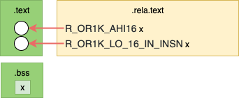
As we recall, to access data in .data and .bss sections simple code
sequences with relocation entries are used. These sequences set and add
registers to build pointers to our data. For example, the below sequence uses 2
relocations to compose a .bss section address into register r11.
Addr.   Machine Code    Assembly             Relocations
0000000c <get_x_addr>:
   c:   19 60 [00 00]   l.movhi r11,[0]      # c  R_OR1K_AHI16 .bss
  10:   44 00  48 00    l.jr r9
  14:   9d 6b [00 00]    l.addi r11,r11,[0]  # 14 R_OR1K_LO_16_IN_INSN .bss
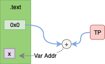
With TLS the code sequences to access our data will also build pointers to our
data, but they need to traverse the TLS data structures.
As the code sequence is read only and will be the same for each thread another
level of indirection is needed, this is provided by the Thread Pointer (TP).
The Thread Pointer points into a data structure that allows us to locate TLS
data sections. The TLS data structure includes:
- Thread Control Block (TCB)
- Dynamic Thread Vector (DTV)
- TLS Data Sections
These are illustrated as below:
  dtv[]   [ dtv[0], dtv[1], dtv[2], .... ]
            counter ^ |      \
               ----/ /        \________
              /     V                  V
/------TCB-------\/----TLS[1]----\   /----TLS[2]----\
| pthread tcbhead | tbss   tdata |   | tbss   tdata |
\----------------/\--------------/   \--------------/
          ^
          |
   TP-----/
Thread Pointer (TP)
The TP is unique to each thread. It provides the starting point to the TLS data
structure.
- The TP points to the Thread Control Block
- On OpenRISC the TP is stored in
r10
- On x86_64 the TP is stored in
$fs
- This is the
*tls pointer passed to the
clone() system call when
using CLONE_SETTLS.
Thread Control Block (TCB)
The TCB is the head of the TLS data structure. The TCB consists of:
pthread - the pthread
struct for the current thread, contains tid etc. Located by TP - TCB size - Pthread sizetcbhead - the tcbhead_t struct, machine dependent, contains pointer to DTV. Located by TP - TCB size.
For OpenRISC tcbhead_t is defined in
sysdeps/or1k/nptl/tls.h as:
typedef struct {
  dtv_t *dtv;
} tcbhead_t
dtv - is a pointer to the dtv array, points to entry dtv[1]
For x86_64 the tcbhead_t is defined in
sysdeps/x86_64/nptl/tls.h
as:
typedef struct
{
  void *tcb;            /* Pointer to the TCB.  Not necessarily the
                           thread descriptor used by libpthread.  */
  dtv_t *dtv;
  void *self;           /* Pointer to the thread descriptor.  */
  int multiple_threads;
  int gscope_flag;
  uintptr_t sysinfo;
  uintptr_t stack_guard;
  uintptr_t pointer_guard;
  unsigned long int vgetcpu_cache[2];
  /* Bit 0: X86_FEATURE_1_IBT.
     Bit 1: X86_FEATURE_1_SHSTK.
   */
  unsigned int feature_1;
  int __glibc_unused1;
  /* Reservation of some values for the TM ABI.  */
  void *__private_tm[4];
  /* GCC split stack support.  */
  void *__private_ss;
  /* The lowest address of shadow stack,  */
  unsigned long long int ssp_base;
  /* Must be kept even if it is no longer used by glibc since programs,
     like AddressSanitizer, depend on the size of tcbhead_t.  */
  __128bits __glibc_unused2[8][4] __attribute__ ((aligned (32)));

  void *__padding[8];
} tcbhead_t;
The x86_64 implementation includes many more fields including:
gscope_flag - Global Scope lock flags used by the runtime linker, for OpenRISC this is stored in pthread.stack_guard - The stack
guard canary stored in
the thread local area. For OpenRISC a global stack guard is stored in .bss.pointer_guard - The pointer
guard stored in the
thread local area. For OpenRISC a global pointer guard is stored in .bss.
Dynamic Thread Vector (DTV)
The DTV is an array of pointers to each TLS data section. The first entry in
the DTV array contains the generation counter. The generation counter is really
just the array size. The DTV can be dynamically resized as more TLS modules are loaded.
The dtv_t type is a union as defined below:
typedef struct {
  void *val;     // Aligned pointer to data/bss
  void *to_free; // Unaligned pointer for free()
} dtv_pointer

typedef union {
  int counter;          // for entry 0
  dtv_pointer pointer;  // for all other entries
} dtv_t
Each dtv_t entry can be either a counter or a pointer. By convention the
first entry, dtv[0] is a counter and the rest are pointers.
Thread Local Storage (TLS)
The initial set of TLS data sections is allocated contiguous with the TCB. Additional TLS
data blocks will be allocated dynamically. There will be one entry for each
loaded module, the first module being the current program. For dynamic
libraries it is lazily initialized per thread.
Local (or TLS[1])
tbss - the .tbss section for the current thread from the current
processes ELF binary.tdata - the .tdata section for the current thread from the current
processes ELF binary.
TLS[2]
tbss - the .tbss section for variables defined in the first shared library loaded by the current processtdata - the .tdata section for variables defined in the first shared library loaded by the current process
The __tls_get_addr() function
The __tls_get_addr() function can be used at any time to traverse the TLS data
structure and return a variable’s address. The function is given a pointer to
an architecture specific argument tls_index.
- The argument contains 2 pieces of data:
- The module index -
0 for the current process, 1 for the first loaded shared
library etc.
- The data offset - the offset of the variable in the
TLS data section
- Internally
__tls_get_addr uses TP to located the TLS data structure
- The function returns the address of the variable we want to access
For static builds the implementation is architecture dependant and defined in
OpenRISC
sysdeps/or1k/libc-tls.c
as:
__tls_get_addr (tls_index *ti)
{
  dtv_t *dtv = THREAD_DTV ();
  return (char *) dtv[1].pointer.val + ti->ti_offset;
}
Note for for static builds the module index can be hard coded to 1 as there
will always be only one module.
For dynamically linked programs the implementation is defined as part of the
runtime dynamic linker in
elf/dl-tls.c
as:
void *
__tls_get_addr (GET_ADDR_ARGS)
{
  dtv_t *dtv = THREAD_DTV ();

  if (__glibc_unlikely (dtv[0].counter != GL(dl_tls_generation)))
    return update_get_addr (GET_ADDR_PARAM);

  void *p = dtv[GET_ADDR_MODULE].pointer.val;

  if (__glibc_unlikely (p == TLS_DTV_UNALLOCATED))
    return tls_get_addr_tail (GET_ADDR_PARAM, dtv, NULL);

  return (char *) p + GET_ADDR_OFFSET;
}
Here several macros are used so it’s a bit hard to follow but there are:
THREAD_DTV - uses TP to get the pointer to the DTV array.GET_ADDR_ARGS - short for tls_index* tiGET_ADDR_PARAM - short for tiGET_ADDR_MODULE - short for ti->ti_moduleGET_ADDR_OFFSET - short for ti->ti_offset
TLS Access Models
As one can imagine, traversing the TLS data structures when accessing each variable
could be slow. For this reason there are different TLS access models that the
compiler can choose to minimize variable access overhead.
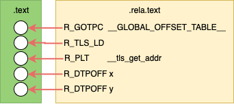
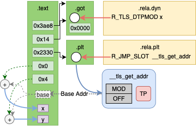
Global Dynamic
The Global Dynamic (GD), sometimes called General Dynamic, access model is the
slowest access model which will traverse the entire TLS data structure for each
variable access. It is used for accessing variables in dynamic shared
libraries.
Before Linking
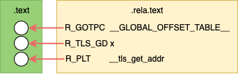
Not counting relocations for the PLT and GOT entries; before linking the .text
contains 1 placeholder for a GOT offset. This GOT entry will contain the
arguments to __tls_get_addr.
After Linking
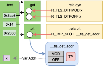
After linking there will be 2 relocation entries in the GOT to be resolved by
the dynamic linker. These are R_TLS_DTPMOD, the TLS module index, and
R_TLS_DTPOFF, the offset of the variable into the TLS module.
Example
File: tls-gd.c
extern __thread int x;

int* get_x_addr() {
  return &x;
}
Code Sequence (OpenRISC)
tls-gd.o:     file format elf32-or1k

Disassembly of section .text:

0000004c <get_x_addr>:
  4c:	18 60 [00 00] 	l.movhi r3,[0]          # 4c: R_OR1K_TLS_GD_HI16	x
  50:	9c 21 ff f8 	l.addi r1,r1,-8
  54:	a8 63 [00 00] 	l.ori r3,r3,[0]         # 54: R_OR1K_TLS_GD_LO16	x
  58:	d4 01 80 00 	l.sw 0(r1),r16
  5c:	d4 01 48 04 	l.sw 4(r1),r9
  60:	04 00 00 02 	l.jal 68 <get_x_addr+0x1c>
  64:	1a 00 [00 00] 	 l.movhi r16,[0]        # 64: R_OR1K_GOTPC_HI16	_GLOBAL_OFFSET_TABLE_-0x4
  68:	aa 10 [00 00] 	l.ori r16,r16,[0]       # 68: R_OR1K_GOTPC_LO16	_GLOBAL_OFFSET_TABLE_
  6c:	e2 10 48 00 	l.add r16,r16,r9
  70:	04 00 [00 00] 	l.jal [0]               # 70: R_OR1K_PLT26	__tls_get_addr
  74:	e0 63 80 00 	 l.add r3,r3,r16
  78:	85 21 00 04 	l.lwz r9,4(r1)
  7c:	86 01 00 00 	l.lwz r16,0(r1)
  80:	44 00 48 00 	l.jr r9
  84:	9c 21 00 08 	 l.addi r1,r1,8
Code Sequence (x86_64)
tls-gd.o:     file format elf64-x86-64

Disassembly of section .text:

0000000000000020 <get_x_addr>:
  20:	48 83 ec 08          	  sub    $0x8,%rsp
  24:	66 48 8d 3d [00 00 00 00] lea    [0](%rip),%rdi  # 28 R_X86_64_TLSGD	x-0x4
  2c:	66 66 48 e8 [00 00 00 00] callq  [0]             # 30 R_X86_64_PLT32	__tls_get_addr-0x4
  34:	48 83 c4 08          	  add    $0x8,%rsp
  38:	c3                   	  retq
Local Dynamic
The Local Dynamic (LD) access model is an optimization for Global Dynamic where
multiple variables may be accessed from the same TLS module. Instead of
traversing the TLS data structure for each variable, the TLS data section address
is loaded once by calling __tls_get_addr with an offset of 0. Next, variables
can be accessed with individual offsets.
Local Dynamic is not supported on OpenRISC yet.
Before Linking
Not counting relocations for the PLT and GOT entries; before linking the .text
contains 1 placeholder for a GOT offset and 2 placeholders for the TLS offsets.
This GOT entry will contain the arguments to __tls_get_addr.
The TLD offsets will be the offsets to our variables in the TLD data section.
After Linking
After linking there will be 1 relocation entry in the GOT to be resolved by
the dynamic linker. This is R_TLS_DTPMOD, the TLS module index, the offset
will be 0x0.
Example
File: tls-ld.c
static __thread int x;
static __thread int y;

int sum() {
  return x + y;
}
Code Sequence (x86_64)
tls-ld.o:     file format elf64-x86-64

Disassembly of section .text:

0000000000000030 <sum>:
  30:	48 83 ec 08          	sub    $0x8,%rsp
  34:	48 8d 3d [00 00 00 00] 	lea    [0](%rip),%rdi   # 37 R_X86_64_TLSLD	x-0x4
  3b:	e8 [00 00 00 00]       	callq  [0]              # 3c R_X86_64_PLT32	__tls_get_addr-0x4
  40:	8b 90 [00 00 00 00]    	mov    [0](%rax),%edx   # 42 R_X86_64_DTPOFF32	x
  46:	03 90 [00 00 00 00]    	add    [0](%rax),%edx   # 48 R_X86_64_DTPOFF32	y
  4c:	48 83 c4 08          	add    $0x8,%rsp
  50:	89 d0                	mov    %edx,%eax
  52:	c3                   	retq
Initial Exec
The Initial Exec (IE) access model does not require traversing the TLS data
structure. It requires that the compiler knows that offset from the TP to the
variable can be computed during link time.
As Initial Exec does not require calling __tls_get_addr is is more efficient
compared the GD and LD access.
Before Linking
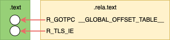
Text contains a placeholder for the got address of the offset. Not counting
relocation entry for the GOT; before linking the .text contains 1 placeholder
for a GOT offset. This GOT entry will contain the TP offset to the variable.
After Linking
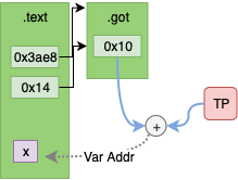
After linking there will be no remaining relocation entries. The .text section
contains the actual GOT offset and the GOT entry will contain the TP offset
to the variable.
Example
File: tls-ie.c
Initial exec C code will be the same as global dynamic, however IE access will
be chosen when static compiling.
extern __thread int x;

int* get_x_addr() {
  return &x;
}
Code Sequence (OpenRISC)
00000038 <get_x_addr>:
  38:	9c 21 ff fc 	l.addi r1,r1,-4
  3c:	1a 20 [00 00] 	l.movhi r17,[0x0]   # 3c: R_OR1K_TLS_IE_AHI16	x
  40:	d4 01 48 00 	l.sw 0(r1),r9
  44:	04 00 00 02 	l.jal 4c <get_x_addr+0x14>
  48:	1a 60 [00 00] 	 l.movhi r19,[0x0]  # 48: R_OR1K_GOTPC_HI16	_GLOBAL_OFFSET_TABLE_-0x4
  4c:	aa 73 [00 00] 	l.ori r19,r19,[0x0] # 4c: R_OR1K_GOTPC_LO16	_GLOBAL_OFFSET_TABLE_
  50:	e2 73 48 00 	l.add r19,r19,r9
  54:	e2 31 98 00 	l.add r17,r17,r19
  58:	85 71 [00 00] 	l.lwz r11,[0](r17)  # 58: R_OR1K_TLS_IE_LO16	x
  5c:	85 21 00 00 	l.lwz r9,0(r1)
  60:	e1 6b 50 00 	l.add r11,r11,r10
  64:	44 00 48 00 	l.jr r9
  68:	9c 21 00 04 	 l.addi r1,r1,4
Code Sequence (x86_64)
0000000000000010 <get_x_addr>:
  10:	48 8b 05 [00 00 00 00] 	   mov    0x0(%rip),%rax   # 13: R_X86_64_GOTTPOFF	x-0x4
  17:	64 48 03 04 25 00 00 00 00 add    %fs:0x0,%rax
  20:	c3                         retq
Local Exec
The Local Exec (LD) access model does not require traversing the TLS data
structure or a GOT entry. It is chosen by the compiler when accessing file
local variables in the current program.
The Local Exec access model is the most efficient.
Before Linking

Before linking the .text section contains one relocation entry for a TP
offset.
After Linking
After linking the .text section contains the value of the TP offset.
Example
File: tls-le.c
In the Local Exec example the variable x is local, it is not extern.
static __thread int x;

int * get_x_addr() {
  return &x;
}
Code Sequence (OpenRISC)
00000010 <get_x_addr>:
  10:	19 60 [00 00] 	l.movhi r11,[0x0]    # 10: R_OR1K_TLS_LE_AHI16	.LANCHOR0
  14:	e1 6b 50 00 	l.add r11,r11,r10
  18:	44 00 48 00 	l.jr r9
  1c:	9d 6b [00 00] 	 l.addi r11,r11,[0]  # 1c: R_OR1K_TLS_LE_LO16	.LANCHOR0
Code Sequence (x86_64)
0000000000000010 <get_x_addr>:
  10:	64 48 8b 04 25 00 00 00 00  mov    %fs:0x0,%rax
  19:	48 05 [00 00 00 00]    	    add    $0x0,%rax  # 1b: R_X86_64_TPOFF32	x
  1f:	c3                   	    retq
Linker Relaxation
As some TLS access methods are more efficient than others we would like to
choose the best method for each variable access. However, we sometimes don’t know
where a variable will come from until link time.
On some architectures the linker will rewrite the TLS access code sequence to
change to a more efficient access model, this is called relaxation.
One type of relaxation performed by the linker is GD to IE relaxation. During compile
time GD relocation may be chosen for extern variables. However, during link time
the variable may be found in the same module i.e. not a shared object which would require
GD access. In this case the access model can be changed to IE.
That’s pretty cool.
The architecture I work on OpenRISC does not support any
of this yet, it requires changes to the compiler and linker. The compiler needs
to be updated to mark sections of the output .text that can be rewritten
(often with added NOP codes). The linker needs to be updated to know how to
identify the relaxation opportunity and perform it.
Summary
In this article we have covered how TLS variables are accessed per thread via
the TLS data structure. Also, we saw how different TLS access models provide
varying levels of efficiency.
In the next article we will look more into how this is implemented in GCC, the
linker and the GLIBC runtime dynamic linker.
Further Reading
29 Nov 2019
Recently I have been working on getting the OpenRISC glibc
port ready for upstreaming. Part of this work has been to run the glibc
testsuite and get the tests to pass. The glibc testsuite
has a comprehensive set of linker and runtime relocation tests.
In order to fix issues with tests I had to learn more than I did before about ELF Relocations
, Thread Local Storage and the binutils linker implementation in BFD. There is a lot of
documentation available, but it’s a bit hard to follow as it assumes certain
knowledge, for example have a look at the Solaris Linker and Libraries
section on relocations. In this article I will try to fill in those gaps.
This will be an illustrated 3 part series covering
All of the examples in this article can be found in my tls-examples
project. Please check it out.
On Linux, you can download it and make it with your favorite toolchain.
By default it will cross compile using an openrisc toolchain.
This can be overridden with the CROSS_COMPILE variable.
For example, to build for your current host.
$ git clone git@github.com:stffrdhrn/tls-examples.git
$ make CROSS_COMPILE=
gcc -fpic -c -o tls-gd-dynamic.o tls-gd.c -Wall -O2 -g
gcc -fpic -c -o nontls-dynamic.o nontls.c -Wall -O2 -g
...
objdump -dr x-static.o > x-static.S
objdump -dr xy-static.o > xy-static.S
Now we can get started.
ELF Segments and Sections
Before we can talk about relocations we need to talk a bit about what makes up
ELF binaries.
This is a prerequisite as relocations and TLS are part of ELF binaries. There
are a few basic ELF binary types:
- Objects (
.o) - produced by a compiler, contains a collection of sections, also call relocatable files.
- Program - an executable program, contains sections grouped into segments.
- Shared Objects (
.so) - a program library, contains sections grouped into segments.
- Core Files - core dump of program memory, these are also ELF binaries
Here we will discuss Object Files and Program Files.
An ELF Object
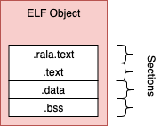
The compiler generates object files, these contain sections of binary data and
these are not executable.
The object file produced by gcc
generally contains .rela.text, .text, .data and .bss sections.
.rela.text - a list of relocations against the .text section.text - contains compiled program machine code.data - static and non static initialized variable values.bss - static and non static non-initialized variables
An ELF Program
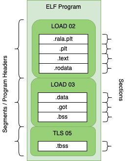
ELF binaries are made of sections and segments.
A segment contains a group of sections and the segment defines how the data should
be loaded into memory for program execution.
Each segment is mapped to program memory by the kernel when a process is created. Program files contain
most of the same sections as objects but there are some differences.
.text - contains executable program code, there is no .rela.text section.got - the global offset table used to access variables, created during link time. May be populated during runtime.
Looking at ELF binaries (readelf)
The readelf tool can help inspect elf binaries.
Some examples:
Reading Sections of an Object File
Using the -S option we can read sections from an elf file.
As we can see below we have the .text, .rela.text, .bss and many other
sections.
$ readelf -S tls-le-static.o
There are 20 section headers, starting at offset 0x604:

Section Headers:
  [Nr] Name              Type            Addr     Off    Size   ES Flg Lk Inf Al
  [ 0]                   NULL            00000000 000000 000000 00      0   0  0
  [ 1] .text             PROGBITS        00000000 000034 000020 00  AX  0   0  4
  [ 2] .rela.text        RELA            00000000 0003f8 000030 0c   I 17   1  4
  [ 3] .data             PROGBITS        00000000 000054 000000 00  WA  0   0  1
  [ 4] .bss              NOBITS          00000000 000054 000000 00  WA  0   0  1
  [ 5] .tbss             NOBITS          00000000 000054 000004 00 WAT  0   0  4
  [ 6] .debug_info       PROGBITS        00000000 000054 000074 00      0   0  1
  [ 7] .rela.debug_info  RELA            00000000 000428 000084 0c   I 17   6  4
  [ 8] .debug_abbrev     PROGBITS        00000000 0000c8 00007c 00      0   0  1
  [ 9] .debug_aranges    PROGBITS        00000000 000144 000020 00      0   0  1
  [10] .rela.debug_arang RELA            00000000 0004ac 000018 0c   I 17   9  4
  [11] .debug_line       PROGBITS        00000000 000164 000087 00      0   0  1
  [12] .rela.debug_line  RELA            00000000 0004c4 00006c 0c   I 17  11  4
  [13] .debug_str        PROGBITS        00000000 0001eb 00007a 01  MS  0   0  1
  [14] .comment          PROGBITS        00000000 000265 00002b 01  MS  0   0  1
  [15] .debug_frame      PROGBITS        00000000 000290 000030 00      0   0  4
  [16] .rela.debug_frame RELA            00000000 000530 000030 0c   I 17  15  4
  [17] .symtab           SYMTAB          00000000 0002c0 000110 10     18  15  4
  [18] .strtab           STRTAB          00000000 0003d0 000025 00      0   0  1
  [19] .shstrtab         STRTAB          00000000 000560 0000a1 00      0   0  1
Reading Sections of a Program File
Using the -S option on a program file we can also read the sections. The file
type does not matter as long as it is an ELF we can read the sections.
As we can see below there is no longer a rela.text section, but we have others
including the .got section.
$ readelf -S tls-le-static
There are 31 section headers, starting at offset 0x32e8fc:

Section Headers:
  [Nr] Name              Type            Addr     Off    Size   ES Flg Lk Inf Al
  [ 0]                   NULL            00000000 000000 000000 00      0   0  0
  [ 1] .text             PROGBITS        000020d4 0000d4 080304 00  AX  0   0  4
  [ 2] __libc_freeres_fn PROGBITS        000823d8 0803d8 001118 00  AX  0   0  4
  [ 3] .rodata           PROGBITS        000834f0 0814f0 01544c 00   A  0   0  4
  [ 4] __libc_subfreeres PROGBITS        0009893c 09693c 000024 00   A  0   0  4
  [ 5] __libc_IO_vtables PROGBITS        00098960 096960 0002f4 00   A  0   0  4
  [ 6] __libc_atexit     PROGBITS        00098c54 096c54 000004 00   A  0   0  4
  [ 7] .eh_frame         PROGBITS        00098c58 096c58 0027a8 00   A  0   0  4
  [ 8] .gcc_except_table PROGBITS        0009b400 099400 000089 00   A  0   0  1
  [ 9] .note.ABI-tag     NOTE            0009b48c 09948c 000020 00   A  0   0  4
  [10] .tdata            PROGBITS        0009dc28 099c28 000010 00 WAT  0   0  4
  [11] .tbss             NOBITS          0009dc38 099c38 000024 00 WAT  0   0  4
  [12] .init_array       INIT_ARRAY      0009dc38 099c38 000004 04  WA  0   0  4
  [13] .fini_array       FINI_ARRAY      0009dc3c 099c3c 000008 04  WA  0   0  4
  [14] .data.rel.ro      PROGBITS        0009dc44 099c44 0003bc 00  WA  0   0  4
  [15] .data             PROGBITS        0009e000 09a000 000de0 00  WA  0   0  4
  [16] .got              PROGBITS        0009ede0 09ade0 000064 04  WA  0   0  4
  [17] .bss              NOBITS          0009ee44 09ae44 000bec 00  WA  0   0  4
  [18] __libc_freeres_pt NOBITS          0009fa30 09ae44 000014 00  WA  0   0  4
  [19] .comment          PROGBITS        00000000 09ae44 00002a 01  MS  0   0  1
  [20] .debug_aranges    PROGBITS        00000000 09ae6e 002300 00      0   0  1
  [21] .debug_info       PROGBITS        00000000 09d16e 0fd048 00      0   0  1
  [22] .debug_abbrev     PROGBITS        00000000 19a1b6 0270ca 00      0   0  1
  [23] .debug_line       PROGBITS        00000000 1c1280 0ce95c 00      0   0  1
  [24] .debug_frame      PROGBITS        00000000 28fbdc 0063bc 00      0   0  4
  [25] .debug_str        PROGBITS        00000000 295f98 011e35 01  MS  0   0  1
  [26] .debug_loc        PROGBITS        00000000 2a7dcd 06c437 00      0   0  1
  [27] .debug_ranges     PROGBITS        00000000 314204 00c900 00      0   0  1
  [28] .symtab           SYMTAB          00000000 320b04 0075d0 10     29 926  4
  [29] .strtab           STRTAB          00000000 3280d4 0066ca 00      0   0  1
  [30] .shstrtab         STRTAB          00000000 32e79e 00015c 00      0   0  1
Key to Flags:
  W (write), A (alloc), X (execute), M (merge), S (strings), I (info),
  L (link order), O (extra OS processing required), G (group), T (TLS),
  C (compressed), x (unknown), o (OS specific), E (exclude),
  p (processor specific)
Reading Segments from a Program File
Using the -l option on a program file we can read the segments.
Notice how segments map from file offsets to memory offsets and alignment.
The two different LOAD type segments are segregated by read only/execute and read/write.
Each section is also mapped to a segment here. As we can see .text is in the first LOAD` segment
which is executable as expected.
$ readelf -l tls-le-static

Elf file type is EXEC (Executable file)
Entry point 0x2104
There are 5 program headers, starting at offset 52

Program Headers:
  Type           Offset   VirtAddr   PhysAddr   FileSiz MemSiz  Flg Align
  LOAD           0x000000 0x00002000 0x00002000 0x994ac 0x994ac R E 0x2000
  LOAD           0x099c28 0x0009dc28 0x0009dc28 0x0121c 0x01e1c RW  0x2000
  NOTE           0x09948c 0x0009b48c 0x0009b48c 0x00020 0x00020 R   0x4
  TLS            0x099c28 0x0009dc28 0x0009dc28 0x00010 0x00034 R   0x4
  GNU_RELRO      0x099c28 0x0009dc28 0x0009dc28 0x003d8 0x003d8 R   0x1

 Section to Segment mapping:
  Segment Sections...
   00     .text __libc_freeres_fn .rodata __libc_subfreeres __libc_IO_vtables __libc_atexit .eh_frame .gcc_except_table .note.ABI-tag
   01     .tdata .init_array .fini_array .data.rel.ro .data .got .bss __libc_freeres_ptrs
   02     .note.ABI-tag
   03     .tdata .tbss
   04     .tdata .init_array .fini_array .data.rel.ro
Reading Segments from an Object File
Using the -l option with an object file does not work as we can see below.
readelf -l tls-le-static.o

There are no program headers in this file.
Relocation entries
As mentioned an object file by itself is not executable. The main reason is that
there are no program headers as we just saw. Another reason is that
the .text section still contains relocation entries (or placeholders) for the
addresses of variables located in the .data and .bss sections.
These placeholders will just be 0 in the machine code. So, if we tried to run
the machine code in an object file we would end up with Segmentation faults (SEGV).
A relocation entry is a placeholder that is added by the compiler or linker when
producing ELF binaries.
The relocation entries are to be filled in with addresses pointing to data.
Relocation entries can be made in code such as the .text section or in data
sections like the .got section. For example:
Resolving Relocations
The diagram above shows relocation entries as white circles.
Relocation entries may be filled or resolved at link-time or dynamically during execution.
Link time relocations
- Place holders are filled in when ELF object files are linked by the linker to create executables or libraries
- For example, relocation entries in
.text sections
Dynamic relocations
- Place holders is filled during runtime by the dynamic linker. i.e. Procedure Link Table
- For example, relocation entries added to
.got and .plt sections which link
to shared objects.
Note: Statically built binaries do not have any dynamic relocations and are not
loaded with the dynamic linker.
In general link time relocations are used to fill in relocation entries in code.
Dynamic relocations fill in relocation entries in data sections.
Listing Relocation Entries
A list of relocations in a ELF binary can printed using readelf with
the -r options.
Output of readelf -r tls-gd-dynamic.o
Relocation section '.rela.text' at offset 0x530 contains 10 entries:
 Offset     Info    Type            Sym.Value  Sym. Name + Addend
00000000  00000f16 R_OR1K_TLS_GD_HI1 00000000   x + 0
00000008  00000f17 R_OR1K_TLS_GD_LO1 00000000   x + 0
00000020  0000100c R_OR1K_GOTPC_HI16 00000000   _GLOBAL_OFFSET_TABLE_ - 4
00000024  0000100d R_OR1K_GOTPC_LO16 00000000   _GLOBAL_OFFSET_TABLE_ + 0
0000002c  00000d0f R_OR1K_PLT26      00000000   __tls_get_addr + 0
...
The relocation entry list explains how to and where to apply the relocation entry.
It contains:
Offset - the location in the binary that needs to be updatedInfo - the encoded value containing the Type, Sym and Addend, which is
broken down to:
Type - the type of relocation (the formula for what is to be performed is defined in the
linker)Sym. Value - the address value (if known) of the symbol.Sym. Name - the name of the symbol (variable name) that this relocation needs to find
during link time.
Addend - a value that needs to be added to the derived symbol address.
This is used to with arrays (i.e. for a relocation referencing a[14] we would have Sym. Name a and an Addend of the data size of a times 14)
Example
File: nontls.c
In the example below we have a simple variable and a function to access it’s
address.
static int x;

int* get_x_addr() {
  return &x;
}
Let’s see what happens when we compile this source.
The steps to compile and link can be found in the tls-examples project hosting
the source examples.
Before Linking
The diagram above shows relocations in the resulting object file as white circles.
In the actual output below we can see that access to the variable x is
referenced by a literal 0 in each instruction. These are highlighted with
square brackets [] below for clarity.
These empty parts of the .text section are relocation entries.
Addr.   Machine Code    Assembly             Relocations
0000000c <get_x_addr>:
   c:   19 60 [00 00]   l.movhi r11,[0]      # c  R_OR1K_AHI16 .bss
  10:   44 00  48 00    l.jr r9
  14:   9d 6b [00 00]    l.addi r11,r11,[0]  # 14 R_OR1K_LO_16_IN_INSN        .bss
The function get_x_addr will return the address of variable x.
We can look at the assembly instruction to understand how this is done. Some background
of the OpenRISC ABI.
- Registers are 32-bit.
- Function return values are placed in register
r11.
- To return from a function we jump to the address in the link register
r9.
- OpenRISC has a branch delay slot, meaning the address after a branch it executed
before the branch is taken.
Now, lets break down the assembly:
l.movhi - move the value [0] into high bits of register r11, clearing the lower bits.l.addi - add the value in register r11 to the value [0] and store the results in r11.l.jr - jump to the address in r9
This constructs a 32-bit value out of 2 16-bit values.
After Linking
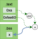
The diagram above shows the relocations have been replaced with actual values.
As we can see from the linker output the places in the machine code that had relocation place holders
are now replaced with values. For example 1a 20 00 00 has become 1a 20 00 0a.
00002298 <get_x_addr>:
    2298:	19 60 00 0a 	l.movhi r11,0xa
    229c:	44 00 48 00 	l.jr r9
    22a0:	9d 6b ee 60 	l.addi r11,r11,-4512
If we calculate 0xa << 16 + -4512 (fee60) we see get 0009ee60. That is the
same location of x within our binary. This we can check with readelf -s
which lists all symbols.
$ readelf -s nontls-static | grep ' x'
    42: 0009ee60     4 OBJECT  LOCAL  DEFAULT   17 x
Types of Relocations
As we saw above, a simple program resulted in 2 different relocation entries just to compose the address of 1 variable.
We saw:
R_OR1K_AHI16R_OR1K_LO_16_IN_INSN
The need for different relacation types comes from the different requirements for the
relocation. Processing of a relocation involves usually a very simple transform
, each relocation defines a different transform. The components of the relocation
definition are:
- Input The input of a relocation formula is always the Symbol Address who’s absolute value is unknown at compile time. But
there may also be other input variables to the formula including:
- Program Counter The absolute address of the machine code address being updated
- Addend The addend from the relocation entry discussed above in the Listing Relocation Entries section
- Formula How the input is manipulated to derive the output value. For example shift right 16 bits.
- Bit-Field Specifies which bits at the output address need to be updated.
To be more specific about the above relocations we have:
| Relocation Type |
Bit-Field |
Formula |
R_OR1K_AHI16 |
simm16 |
S >> 16 |
R_OR1K_LO_16_IN_INSN |
simm16 |
S && 0xffff |
The Bit-Field described above is simm16 which means update the lower 16-bits
of the 32-bit value at the output offset and do not disturb the upper 16-bits.
 +----------+----------+
 |          |  simm16  |
 | 31    16 | 15     0 |
 +----------+----------+
There are many other Relocation Types with difference Bit-Fields and Formulas.
These use different methods based on what each instruction does, and where each instruction
encodes its immediate value.
For full listings refer to architecture manuals.
Take a look and see if you can understand how to read these now.
Summary
In this article we have discussed what ELF binaries are and how they can be read.
We have talked about how from compilation to linking to runtime, relocation entries
are used to communicate which parts of a program remain to be resolved. We
then discussed how relocation types provide a formula and bit-mask for updating
the places in ELF binaries that need to be filled in.
In the next article we will discuss how Thread Local Storage works, both link-time
and runtime relocation entries play big part in how TLS works.
Further Reading
21 Oct 2019
This is an ongoing series of posts on the Marocchino CPU, an open source out-of-order
OpenRISC cpu. In this series we are reviewing the
Marocchino and it’s architecture. If you haven’t already I suggest you start of
by reading the intro in Marocchino in Action.
In the last article, Marocchino Instruction Pipeline we discussed the
architecture of the CPU. In this article let’s look at how Marocchino achieves
out-of-order execution using the Tomasulo algorithm.
Achieving Out-of-Order Execution
In a traditional pipelined CPU the goal is retire one instruction
per clock cycle. Any pipeline stall means an execution clock cycle will be lost.
One method for reducing the affect of pipeline stalls is instruction parallelization. In 1993
the Intel Pentium
processor was one of the first consumer CPUs to achieve this with it’s dual U
and V integer pipelines.
The pentium U and V pipelines require certain coding
techniques to take full
advantage. Achieving more parallelism requires more sophisticated data hazard
detection and instruction scheduling. Introduced with the IBM System/360 in the
60’s by Robert Tomasulo, the Tomosulo Algorithm provides the building blocks to
allow for multiple instruction execution parallelism. Generally speaking no special programming is needed to
take advantage of instruction parallelism on a processor implementing Tomasulo
algorithm.
Though the technique of out-of-order CPU execution with Tomasulo’s algorithm had
been designed in the 60’s it did not make its way into popular consumer hardware
until the Pentium Pro in the 1995.
Further Pentium revisions such as the Pentium III, Pentium 4 and Core
architectures are based on this same architecture. Understanding
this architecture is a key to understanding modern CPUs.
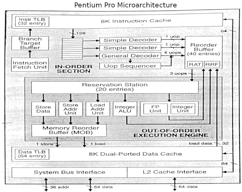
In this article we will point out comparisons between the Marocchino and Pentium pro
who’s architecture can be seen in the below diagram.
The Marocchino implements the Tomasulo algorithm in a CPU that can be synthesized
and run on an FPGA. Let’s dive into the implementation by breaking down the
building blocks used in Tomasulo’s algorithm and how they have been implemented in
Marocchino.
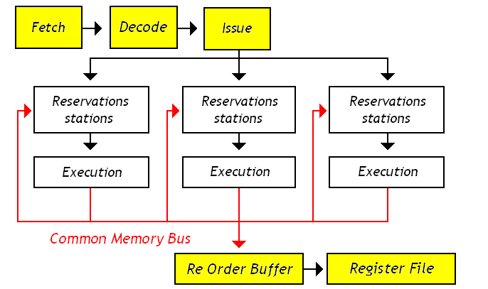
Tomasulo Building blocks
Besides the basic CPU modules like Instruction Fetch, Decode and Register File,
the building blocks that are used in the Tomasulo algorithm are as follows:
- Reservation Station - A
queue where decoded instructions are placed before they can be
executed. Instructions are placed in the queue with their decoded operation
and available arguments. If any arguments are not available the reservation
station will wait until the arguments are available before executing.
- Execution Units - The execution units include the Arithmetic
Logic Unit (ALU), Memory Load/Store Unit or FPU is responsible for performing
the instruction operation.
- Re-order Buffer (ROB) - A ring
buffer which manages the order in which instructions are retired. In Marocchino
the implementation is slightly simplified and called the Order Control Buffer (OCB).
- Instruction Ids - As an instruction is queued into the ROB, or OCB in Marocchino
it is assigned an Instruction Id which is used to track the instruction in different
components in Marocchino code this is called the
extaddr.
- Register Allocation Table (RAT) - A table used for data hazard resolution.
The RAT table has one cell per OpenRISC general purpose register, 32 entries.
Each RAT cell indicates if a register is busy being produced by a queued
instruction and which instruction will produce it.
- Common Data Bus - Execution units present their result to all reservation stations
along with the register file. Writing to the reservation station provides
immediate resolution of data hazards. The link between execution units,
reservation stations and register file is referred to as the common data bus.
The below diagram shows how these components are arranged in the Marocchino processor.
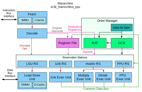
Resolving Data Hazards
As mentioned above the goal of a pipelined architecture is to retire one
instruction per clock cycle.
Pipelining helps achieve
this by splitting an instruction into pipeline stages i.e. Fetch, Decode,
Execute, Load/Store and Register Write Back. If one instruction depends on the
results produced by a previous instruction will be a problem as register
write back of the previous instruction may not complete before registers are
read during the Decode phase of a instruction. This and other types of dependencies
between pipeline stages are called
hazards, and
they must be avoided.
The Tomasulo algorithm with its Reservation Stations, Register Allocation Tables
and other building blocks try to avoid hazards causing pipeline stalls. Let’s look
at a simple example to see how this is done.
- instruction 1 -
b = a * 2
- instruction 2 -
x = a + b
- instruction 3 -
y = x / y
Here we can see that instruction 2 depends on instruction 1 as the addition
of a + b cannot be performed until b is produced by instruction 1.
Let’s assume that instruction 1 is currently executing on the MULTIPLY unit.
The CPU decodes instruction 2, instead of detecting a data hazard and stalling
the pipeline instruction 2 will be placed in the reservation station of the
ADD execution unit. The RAT indicates that b is busy and being produced by
insruction 1. This means instruction 2 cannot execute right away. Next, we
can look at instruction 3 and place it onto the reservation station of the
DIVIDE execution unit. As instruction 3 has no hazards for x and y it
can proceed directly to execution, even before instruction 2 is ready for
execution.
Note, if a required reservation station is full the pipeline will stall.
Register Renaming
As mentioned above, execution units will present their output onto the common
data bus wrbk_result and the data will be written into reservation stations.
Writing the register to the reservation station may occur before writing
back to the register file. This is what register renaming is, as the
register input does not come directly from the register file.
Instruction Id
When an instruction is issued it may be registered in the RAT, OCB and Reservation
Station. It is assigned an Instruction Id for tracking purposes. In Marocchino
this is called the extadr and is 3 bits wide. It is generated by the simple
instruction ID generation logic.
The is implemented in or1k_marocchino_oman.v with the following counter
logic which generates a new extadr every time an instruction is decoded.
  // extension to DEST, FLAG or CARRY
  // Zero value is reserved as "not used"
  localparam [DEST_EXTADR_WIDTH-1:0] EXTADR_MAX = ((1 << DEST_EXTADR_WIDTH) - 1);
  localparam [DEST_EXTADR_WIDTH-1:0] EXTADR_MIN = 1;
  // ---
  reg  [DEST_EXTADR_WIDTH-1:0] dcod_extadr_r;
  wire [DEST_EXTADR_WIDTH-1:0] extadr_adder;
  // ---
  assign extadr_adder = (dcod_extadr_r == EXTADR_MAX) ? EXTADR_MIN : (dcod_extadr_r + 1'b1);
  // ---
  always @(posedge cpu_clk) begin
    if (pipeline_flush_i)
      dcod_extadr_r <= {DEST_EXTADR_WIDTH{1'b0}};
    else if (padv_dcod_i)
      dcod_extadr_r <= fetch_valid_i ? extadr_adder : dcod_extadr_r;
  end // @clock
  // support in-1clk-unit forwarding
  assign dcod_extadr_o = dcod_extadr_r;
Every instruction that is queued by the order manager is designated
an extadr. This allows components like the reservation station and RAT tables
to track when an instruction starts and completes executing.
The interactions between the extadr and other components are as follows.
During decode:
- the ID generator generates the
extaddr by incrementing a counter.
- the OCB registers the
extaddr along with other decoded instruction details
- the RAT registers an
extaddr for the decoded instruction to indicate which
instruction will resolve a hazard.
During execution:
- the OCB broadcasts the
extaddr of the oldest instruction registered in a FIFO
fashion. This is to indicate which instruction is to be retired and ensures
instructions are retired in order.
- the RAT outputs the
extaddr indicating which queued instruction will produce a register
- the RAT receives an
extaddr from the OCB output to clear allocation flags
- the Reservation Station receives the
extaddr with hazards to track when
instructions have finished and results are available.
Register Allocation Table
The register allocation table (RAT), sometimes called register alias table, keeps
track of which registers are currently in progress of being generated by pending
instructions. This is used to derive and resolve hazards.
The outputs of the RAT cell are:
rat_rd_extadr_o - indicates which extadr instruction has been allocated to
generate this register.
This will be updated with decod_extadr_i when padv_exec_i goes high.rat_rd_alloc_o - indicates that this register is currently allocated to an
instruction which is not yet complete.
This will be set when padv_exec_i goes high, decod_rfd_we_i is high,
and dcod_rfd_adr_i is equal to GPR_ADR.
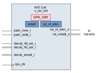
The RAT table is made of 32 rat_cell modules; one cell per register. The
register which the cell is allocated to is stored within GPR_ADR in the rat
cell.
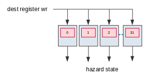
Outputs of the RAT are registered to reservation stations. The hazards are
derived with the following logic in or1k_marocchino_oman.v.
The omn2dec_hazard_d1a1_o hazard means that the argument a of the decoded
instruction will be resolved when the instruction with extadr in omn2dec_extadr_dxa1_o is
retired. The 2 in d2, a2 and b2 represent the 2nd register used in 64-bit
FPU instructions.
  //  # relative operand A1
  assign omn2dec_hazard_d1a1_o = rat_rd1_alloc[dcod_rfa1_adr_i] & dcod_rfa1_req_i;
  assign omn2dec_hazard_d2a1_o = rat_rd2_alloc[dcod_rfa1_adr_i] & dcod_rfa1_req_i;
  assign omn2dec_extadr_dxa1_o = rat_extadr[dcod_rfa1_adr_i];
  //  # relative operand B1
  assign omn2dec_hazard_d1b1_o = rat_rd1_alloc[dcod_rfb1_adr_i] & dcod_rfb1_req_i;
  assign omn2dec_hazard_d2b1_o = rat_rd2_alloc[dcod_rfb1_adr_i] & dcod_rfb1_req_i;
  assign omn2dec_extadr_dxb1_o = rat_extadr[dcod_rfb1_adr_i];
  //  # relative operand A2
  assign omn2dec_hazard_d1a2_o = rat_rd1_alloc[dcod_rfa2_adr_i] & dcod_rfa2_req_i;
  assign omn2dec_hazard_d2a2_o = rat_rd2_alloc[dcod_rfa2_adr_i] & dcod_rfa2_req_i;
  assign omn2dec_extadr_dxa2_o = rat_extadr[dcod_rfa2_adr_i];
  //  # relative operand B2
  assign omn2dec_hazard_d1b2_o = rat_rd1_alloc[dcod_rfb2_adr_i] & dcod_rfb2_req_i;
  assign omn2dec_hazard_d2b2_o = rat_rd2_alloc[dcod_rfb2_adr_i] & dcod_rfb2_req_i;
  assign omn2dec_extadr_dxb2_o = rat_extadr[dcod_rfb2_adr_i];
Reservation Stations
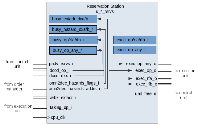
The reservation station receives an instruction from the decode stage and queues
it until all hazards are resolved and the execution unit is free.
Each reservation station has one busy slot and one execution slot. In the
Pentium Pro there were 20 reservation station slots, the Marocchino has 5 or 10
depending if you count the execution slots.
Reservation stations are populated when the pipeline advance padv_rsrvs_i signal comes.
An instruction may be forwarded directly to execution if there are no hazards
and the execution unit is free.
The reservation station resolves hazards by watching and comparing wrbk_extadr_i
with the busy_extadr_dxa_r and busy_extadr_dxb_r registers. If the two match
it means that the instruction producing register A or B has finished writing back
its results and the hazard can be cleared.
Writeback forwarding is handled via the following verilog multiplexer and register logic.
The first bit is used to register the decoded values dcod_rf* from the register
file otherwise we watch for inputs from the forwarding logic. If there is a pending hazard
results are forwarded from the common data bus, otherwise results are maintained.
  // BUSY stage operands A1 & B1
  always @(posedge cpu_clk) begin
    if (padv_rsrvs_i) begin
      busy_rfa1_r <= dcod_rfa1;
      busy_rfb1_r <= dcod_rfb1;
    end
    else begin
      busy_rfa1_r <= busy_rfa1;
      busy_rfb1_r <= busy_rfb1;
    end
  end // @clock

  // Forwarding
  //  operand A1
  assign busy_rfa1 =  busy_hazard_d1a1_r ? wrbk_result1_i :
                     (busy_hazard_d2a1_r ? wrbk_result2_i : busy_rfa1_r);
  //  operand B1
  assign busy_rfb1 =  busy_hazard_d1b1_r ? wrbk_result1_i :
                     (busy_hazard_d2b1_r ? wrbk_result2_i : busy_rfb1_r);
When all hazard flags are cleared the contents of busy_op_r , busy_rfa_r and
busy_rfb_r will be transferred to exec_op_any_r, exec_op_r, etc. They
are presented on the outputs and the execution unit can take them and start processing.
The unit_free_o output signals the control unit that the reservation station
is free and can be issued another instruction. The signal goes high when all hazards
are cleared and the busy state transfers to exec.
Execution Units
In Marocchino the execution units (also referred to as functional units)
execute instructions which it receives from the reservation stations.
The execution units in Marocchino are:
or1k_marocchino_int_1clk - handles integer instructions which can complete
in 1 clock cycle. This includes SHIFT, ADD, AND, OR etc.or1k_marocchino_int_div - handles integer DIVIDE operations.or1k_marocchino_int_mul - handles integer MULTIPLY operations.or1k_marocchino_lsu - handles memory load store operations. It interfaces
with the data cache, MMU and memory bus.pfpu_marocchino_top - handles floating point operations. These include
ADD, MULTIPLY, CMP, I2F etc.
Handshake signals between the reservation station and execution units are used
to issue operations to execution units.
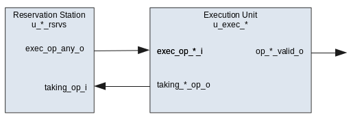
The taking_op_i is the signal from the execution unit signalling it has
received the op and the reservation station will clear all exec_*_o output
signals.
Order Control Buffer
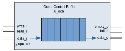
In the Marocchino the Order Control Buffer (OCB) is the in order retirement
unit. It can retire a single instruction at a time. The implementation is a 7
entry FIFO queue. This is much less than the Pentium Pro which contains 40
slots. The OCB receives a single instruction at time from the decoder and
broadcasts the oldest instruction for other components to see. Instructions are
retired after execution write back is complete.
If the OCB output indicates a branch instruction or an exception, branch logic
is invoked. Instead of waiting for write back to a register the write back logic
in the Marocchino will perform the branch operations. This may include flushing
the OCB. Special care is taken to handle branch delay slot instruction execution.
The OCB is different from a traditional Tomasulo Reorder Buffer (ROB) in that it
does not store any execution write back results.
Each OCB entry stores:
- The Instruction ID
extaddr
- The type of instruction
- The register destination addresses used for write back
- Any Fetch and Decode exceptions
This can be seen as defined by the ocbi and ocbi wire buses in
or1k_marocchino_oman.v.
  // --- OCB-Controls input ---
  wire  [OCBT_MSB:0] ocbi;
  assign ocbi =
    {
      // --- pipeline [C]ontrol flags ---
      dcod_extadr_r, // OCB-Controls entrance
      dcod_op_ls_i, // OCB-Controls entrance
      dcod_op_fpxx_cmp_i, // OCB-Controls entrance
      dcod_op_fpxx_arith_i, // OCB-Controls entrance
      dcod_op_mul_i, // OCB-Controls entrance
      dcod_op_div_i, // OCB-Controls entrance
      dcod_op_1clk_i, // OCB-Controls entrance
      dcod_op_jb_r, // OCB-Controls entrance
      dcod_op_push_wrbk_i, // OCB-Controls entrance
      // --- instruction [A]ttributes ---
      pc_decode_i, // OCB-Attributes entrance
      dcod_rfd2_adr_i, // OCB-Attributes entrance
      dcod_rfd2_we_i, // OCB-Attributes entrance
      dcod_rfd1_adr_i, // OCB-Attributes entrance
      dcod_rfd1_we_i, // OCB-Attributes entrance
      dcod_delay_slot_i, // OCB-Attributes entrance
      dcod_op_rfe_i, // OCB-Attributes entrance
      // Flag that istruction is restartable
      interrupts_en, // OCB-Attributes entrance
      // Combined IFETCH/DECODE an exception flag
      dcod_an_except_fd_i, // OCB-Attributes entrance
      // FETCH & DECODE exceptions
      dcod_fetch_except_ibus_err_r, // OCB-Attributes entrance
      dcod_fetch_except_ipagefault_r, // OCB-Attributes entrance
      dcod_fetch_except_itlb_miss_r, // OCB-Attributes entrance
      dcod_except_illegal_i, // OCB-Attributes entrance
      dcod_except_syscall_i, // OCB-Attributes entrance
      dcod_except_trap_i // OCB-Attributes entrance
    };

  // --- INSN OCB input ---
  wire [OCBT_MSB:0] ocbo;
Common Data Bus
As discussed above the common data collects write back results from execution units
and routes them for write back.
This can be seen in the or1k_marocchino_cpu.v
as below.
  // --- regular ---
  always @(wrbk_1clk_result       or wrbk_div_result or wrbk_mul_result or
           wrbk_fpxx_arith_res_hi or wrbk_lsu_result or wrbk_mfspr_result)
  begin
    wrbk_result1 = wrbk_1clk_result       | wrbk_div_result | wrbk_mul_result |
                   wrbk_fpxx_arith_res_hi | wrbk_lsu_result | wrbk_mfspr_result;
  end

  // --- FPU64 extention ---
  assign wrbk_result2 = wrbk_fpxx_arith_res_lo;
Conclusion
Tomasulo’s algorithm is still relevant today and used in many processors.
Marocchino provides an accessible implementation. Marocchino is however, not
super-scalar, while Pentium Pro can decode up to 4 instructions at a time the Marocchino
can only decode 1 at a time.
Furthermore many improvements can be made to Marocchino to increase performance. Including:
- Full featured reorder buffer
- Parallel instruction decoding
- Speculative execution; or should we?
- More reservation station slots
However, these come with a cost of size on the FPGA. If you are interested in helping
out please feel free to contribute.
If anything in this article could be improved, more timing diagrams, typos or fixes
for diagrams please send me a message on twitter.
Further Reading and Sources
18 Jul 2019
This is an ongoing series of posts on the Marocchino CPU, an open source out-of-order
OpenRISC cpu. In this series we will review the Marocchino and it’s architecture.
If you haven’t already I suggest you start of by reading the intro in Marocchino in Action.
In the last article, Marocchino in Action we discussed the history of
the CPU and how to setup setup a development environment for it. In this
article let’s look a bit deeper into how the Marocchino CPU works.
We will look at how an instruction flows through the Marocchino pipeline.
Marocchino Architecture
The Marocchino source code is available on
github
and is easy to navigate. We have these directories:
rtl/verilog - the core verilog code, with toplevel modules
or1k_marocchino_top.v - top level module, connects CPU to wishbone busor1k_marocchino_cpu.v - CPU module, connects CPU pipeline
rtl/verilog/pfpu_marocchino - the FPU implementation
pfpu_marocchino_top.v - FPU module, wires together FPU components
bench - test bench harness monitor modulesdoc - design documentation
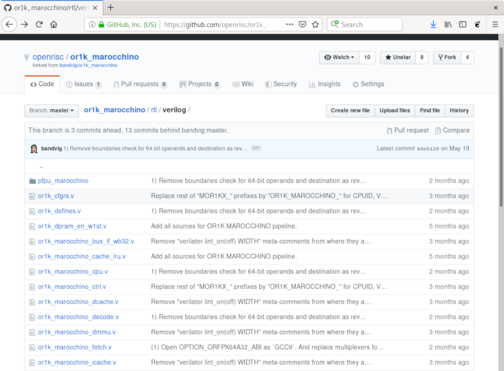
At first glance of the code the Marocchino may look like a traditional 5 stage
RISC pipeline. It has
fetch, decode, execution, load/store and register write back modules which you
might picture in your head as follows:
  PIPELINE CRTL - progress/stall the pipeline
  (or1k_marocchino_ctrl.v)

  INSTRUCTION PIPELINE - process an instruction

                        |
                        V
/                     FETCH                     \
\ (or1k_marocchino_fetch.v)                     /
                        |
                        V
/                     DECODE                    \
\ (or1k_marocchino_decode.v)                    /
                        |
                        V
/                     EXECUTE                   \
| (or1k_marocchino_int_1clk.v) ALU              |
| (or1k_marocchino_int_div.v)  DIVISION         |
\ (or1k_marocchino_int_mul.v)  MULTIPLICATION   /
                        |
                        V
/                   LOAD STORE                  \
\ (or1k_marocchino_lsu.v)      TO/FROM RAM      /
                        |
                        V
/                   WRITE BACK                  \
\ (or1k_marocchino_rf.v)                        /
However, once you look a bit closer you notice some things that are different.
The top-level module
or1k_marocchino_cpu
connects the modules and shows:
- Between the decode and execution units there are reservation stations.
- Along with the control unit, there is an order manager module which provides control signals.
- The load/store execution unit is done as part of the execution stage.
What this CPU is is a super-scalar instruction pipeline with in order instruction
retirement implementing the Tomasulo algorithm.
A simplified view of the CPU’s internal module layout is as per the below diagram.
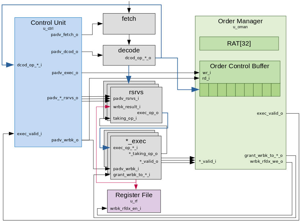
Pipeline Controls
The marocchino has two modules for coordinating pipeline stage instruction propagation. The
control unit and the order manager.
Control Unit
The control unit of the CPU is in charge of watching over the pipeline stages
and signalling when operations can transfer from one stage to the next. The
Marocchino does this with a series of pipeline advance (padv_*) signals. In
general for the best efficiency all padv_* wires should be high at all times
allowing instructions to progress on every clock cycle. But as we will see in
reality, this is difficult to achieve due to pipeline stall scenarios like cache
misses and branch prediction misses. The padv_* signals include:
padv_fetch_o
The padv_fetch_o signal instructs the instruction fetch unit to progress.
Internally the fetch unit has 3 stages. The instruction fetch unit interacts
with the instruction cache and instruction memory management unit (MMU).
The padv_fetch_o signal goes low and the pipeline stalls when the decode
module is busy (dcod_emtpy_i is low). The signal dcod_empty_i comes from
the Decode module and indicates that an instruction can be accepted by the
decode stage.
This is represented by this assign in or1k_marocchino_ctrl.v:
Note The stepping and pstep[] signals are related to debug single stepping, and can be
ignored for our purposes.
  // Advance IFETCH
  // Stepping condition is close to the one for DECODE
  assign padv_fetch_o = padv_all & ((~stepping) | (dcod_empty_i & pstep[0])); // ADV. IFETCH
padv_dcod_o
The padv_dcod_o signal instructs the instruction decode stage to output
decoded operands. The decode unit is one stage, if padv_dcod_o is high, it
will decode the instruction input every cycle.
The padv_dcod_o signal goes low if the destination reservation station for the
operands cannot accept an instruction.
This is represented by this assign in or1k_marocchino_ctrl.v:
  // Advance DECODE
  assign padv_dcod_o = padv_all & (~wrbk_rfdx_we_i) & // ADV. DECODE
    (((~stepping) & dcod_free_i & (dcod_empty_i | ena_dcod)) | // ADV. DECODE
       (stepping  & dcod_empty_i & pstep[0])); // ADV. DECODE
padv_exec_o and padv_*_rsrvs_o
The padv_exec_o signal to order manager enqueues decoded ops into the Order Control
Buffer (OCB). The OCB is a FIFO
queue which keeps track of the order instructions have been decoded.
The padv_*_rsrvs_o signal wired one of the reservation stations
enables registering of an instruction into a reservation station. There is one
padv_*_rsrvs_o signal and reservation station per execution unit. They are:
padv_1clk_rsrvs_o - to the reservation station for single clock ALU operationspadv_muldiv_rsrvs_o - to the reservation station for multiply and divide
operations. Divide operations take 32 clock cycles. Multiply operations
execute with 2 clock cycles.padv_fpxx_rsrvs_o - to the reservation station for the floating point unit
(FPU). There are multiple FPU operations including multiply, divide, add,
subtract, comparison and conversion between integer and floating point.padv_lsu_rsrvs_o - to the reservation station for the load store unit. The
load store unit will load data from memory
to registers or store data from registers to memory. It interacts with the
data cache and data MMU.
Both padv_exec_o and padv_*_rsrvs_o are dependent on the execution units being
ready and both signals will go high or low at the same time.
This is represented by the assign in or1k_marocchino_ctrl.v:
  // Advance EXECUTE (push OCB & clean up  DECODE)
  assign padv_exec_o         = ena_exec         & padv_an_exec_unit;
  // Per execution unit (or reservation station) advance
  assign padv_1clk_rsrvs_o   = ena_1clk_rsrvs   & padv_an_exec_unit;
  assign padv_muldiv_rsrvs_o = ena_muldiv_rsrvs & padv_an_exec_unit;
  assign padv_fpxx_rsrvs_o   = ena_fpxx_rsrvs   & padv_an_exec_unit;
  assign padv_lsu_rsrvs_o    = ena_lsu_rsrvs    & padv_an_exec_unit;
padv_wrbk_o
The padv_wrbk_o signal to the execution units will go active when exec_valid_i is active
and will finalize writing back the execution results. The padv_wrbk_o signal to
the order manager will retire the oldest instruction from the OCB.
This is represented by this assign in or1k_marocchino_ctrl.v:
  // Advance Write Back latches
  wire   exec_valid_l = exec_valid_i | op_mXspr_valid;
  assign padv_wrbk_o  = exec_valid_l & padv_all & (~wrbk_rfdx_we_i) & ((~stepping) | pstep[2]);
An astute reader would notice that there are no pipeline advance (padv_*)
signals to each of the execution units. This is where the order manager comes
in.
Order Manager
The order manager ensures that instructions are retired in the same order that they are decoded.
It contains a register allocation table (RAT) for hazard resolution and the OCB.
We will go into more depth on the RAT in the next article, but for now let’s look
at how the order manager interacts with the instruction pipeline flow.
exec_valid_o
As the OCB is a FIFO queue the output port presents the oldest non retired
instruction to the order manager. The exec_valid_o signal to the control unit
will go active when the *_valid_i signal from the execution unit and the OCB
output instruction match.
This is represented by this assign in or1k_marocchino_oman.v:
  assign exec_valid_o =
    (op_1clk_valid_l          & ~ocbo[OCBTC_JUMP_OR_BRANCH_POS]) | // EXEC VALID: but wait attributes for l.jal/ljalr
    (exec_jb_attr_valid       &  ocbo[OCBTC_JUMP_OR_BRANCH_POS]) | // EXEC VALID
    (div_valid_i              &  ocbo[OCBTC_OP_DIV_POS])         | // EXEC VALID
    (mul_valid_i              &  ocbo[OCBTC_OP_MUL_POS])         | // EXEC VALID
    (fpxx_arith_valid_i       &  ocbo[OCBTC_OP_FPXX_ARITH_POS])  | // EXEC VALID
    (fpxx_cmp_valid_i         &  ocbo[OCBTC_OP_FPXX_CMP_POS])    | // EXEC VALID
    (lsu_valid_i              &  ocbo[OCBTC_OP_LS_POS])          | // EXEC VALID
                                 ocbo[OCBTC_OP_PUSH_WRBK_POS];     // EXEC VALID
The OCB helps the order manager ensure that instructions are retired in the same
order that they are decoded.
grant_wrbk_*_o
The grant_wrbk_*_o signal to the execution units will go active depending on
the OCB output port instruction.
This is represented by this assign in
or1k_marocchino_oman.v:
  // Grant Write-Back-access to units
  assign grant_wrbk_to_1clk_o        = ocbo[OCBTC_OP_1CLK_POS];
  assign grant_wrbk_to_div_o         = ocbo[OCBTC_OP_DIV_POS];
  assign grant_wrbk_to_mul_o         = ocbo[OCBTC_OP_MUL_POS];
  assign grant_wrbk_to_fpxx_arith_o  = ocbo[OCBTC_OP_FPXX_ARITH_POS];
  assign grant_wrbk_to_lsu_o         = ocbo[OCBTC_OP_LS_POS];
  assign grant_wrbk_to_fpxx_cmp_o    = ocbo[OCBTC_OP_FPXX_CMP_POS];
The grant_wrbk_*_o signal along with the padb_wrbk_o signal signal an
execution unit that it can write back its result to the register file / RAT /
reservation station.
wrbk_rfd1_we_o, wrbk_rfd2_we_o and wrbk_rfdx_we_o
The wrbk_rfd1_we_o and wrbk_rfd2_we_o signals enable writeback
to the register file. There are 2 signals because some 64-bit FPU instructions
require writing results to 2 registers. When there is just a single register to write
only signal wrbk_rfd1_we_o is used. When there are two results, writing happens
in 2-stages, first wrbk_rfd1_we_o signals the write back to register 1 then in
the next cycle wrbk_rfd2_we_o signals the write back to register 2.
The wrbk_rfdx_we_o signal to the control unit stalls the pipeline to allow
the second write to complete.
This is represented by this logic in
or1k_marocchino_oman.v:
  // instuction requests write-back
  wire exec_rfd1_we = ocbo[OCBTA_RFD1_WRBK_POS];
  wire exec_rfd2_we = ocbo[OCBTA_RFD2_WRBK_POS];

...

  // 1-clock Write-Back-pulses
  //  # for D1
  always @(posedge cpu_clk) begin
    if (padv_wrbk_i)
      wrbk_rfd1_we_o <= exec_rfd1_we;
    else
      wrbk_rfd1_we_o <= 1'b0;
  end // @clock

  //  # for D2 we delay WriteBack for 1-clock
  //    to split write into RF from D1
  always @(posedge cpu_clk) begin
    if (cpu_rst) begin
      wrbk_rfdx_we_o <= 1'b0; // flush
      wrbk_rfd2_we_o <= 1'b0; // flush
    end
    else if (wrbk_rfd2_we_o) begin
      wrbk_rfdx_we_o <= 1'b0; // D2 write done
      wrbk_rfd2_we_o <= 1'b0; // D2 write done
    end
    else if (wrbk_rfdx_we_o)
      wrbk_rfd2_we_o <= 1'b1; // do D2 write
    else if (padv_wrbk_i)
      wrbk_rfdx_we_o <= exec_rfd2_we;
  end // @clock
The padv_wrbk_i signal from the control unit to the order manager also takes
care of dequeuing the last instruction from the OCB. With that and the
writebacks completed the instruction is said to be retired.
Conclusion
The Marocchino instruction pipeline is not very complicated while still being
full featured including Caches, MMU and FPU. We have mentioned
a few structures such as Reservation Station and RAT which we haven’t gone into
much details on. These help implement out-of-order superscalar execution using
Tomasulo’s algorithm. In the next article we will go into more details on these
components and how Tomasulo works.