This is an ongoing series of posts on the Marocchino CPU, an open source out-of-order OpenRISC cpu. In this series we will review the Marocchino and it’s architecture. If you haven’t already I suggest you start of by reading the intro in Marocchino in Action.
In the last article, Marocchino in Action we discussed the history of the CPU and how to setup setup a development environment for it. In this article let’s look a bit deeper into how the Marocchino CPU works.
We will look at how an instruction flows through the Marocchino pipeline.
Marocchino Architecture
The Marocchino source code is available on github and is easy to navigate. We have these directories:
rtl/verilog- the core verilog code, with toplevel modulesor1k_marocchino_top.v- top level module, connects CPU to wishbone busor1k_marocchino_cpu.v- CPU module, connects CPU pipeline
rtl/verilog/pfpu_marocchino- the FPU implementationpfpu_marocchino_top.v- FPU module, wires together FPU components
bench- test bench harness monitor modulesdoc- design documentation

At first glance of the code the Marocchino may look like a traditional 5 stage RISC pipeline. It has fetch, decode, execution, load/store and register write back modules which you might picture in your head as follows:
  PIPELINE CRTL - progress/stall the pipeline
  (or1k_marocchino_ctrl.v)

  INSTRUCTION PIPELINE - process an instruction

                        |
                        V
/                     FETCH                     \
\ (or1k_marocchino_fetch.v)                     /
                        |
                        V
/                     DECODE                    \
\ (or1k_marocchino_decode.v)                    /
                        |
                        V
/                     EXECUTE                   \
| (or1k_marocchino_int_1clk.v) ALU              |
| (or1k_marocchino_int_div.v)  DIVISION         |
\ (or1k_marocchino_int_mul.v)  MULTIPLICATION   /
                        |
                        V
/                   LOAD STORE                  \
\ (or1k_marocchino_lsu.v)      TO/FROM RAM      /
                        |
                        V
/                   WRITE BACK                  \
\ (or1k_marocchino_rf.v)                        /
However, once you look a bit closer you notice some things that are different. The top-level module or1k_marocchino_cpu connects the modules and shows:
- Between the decode and execution units there are reservation stations.
- Along with the control unit, there is an order manager module which provides control signals.
- The load/store execution unit is done as part of the execution stage.
What this CPU is is a super-scalar instruction pipeline with in order instruction retirement implementing the Tomasulo algorithm.
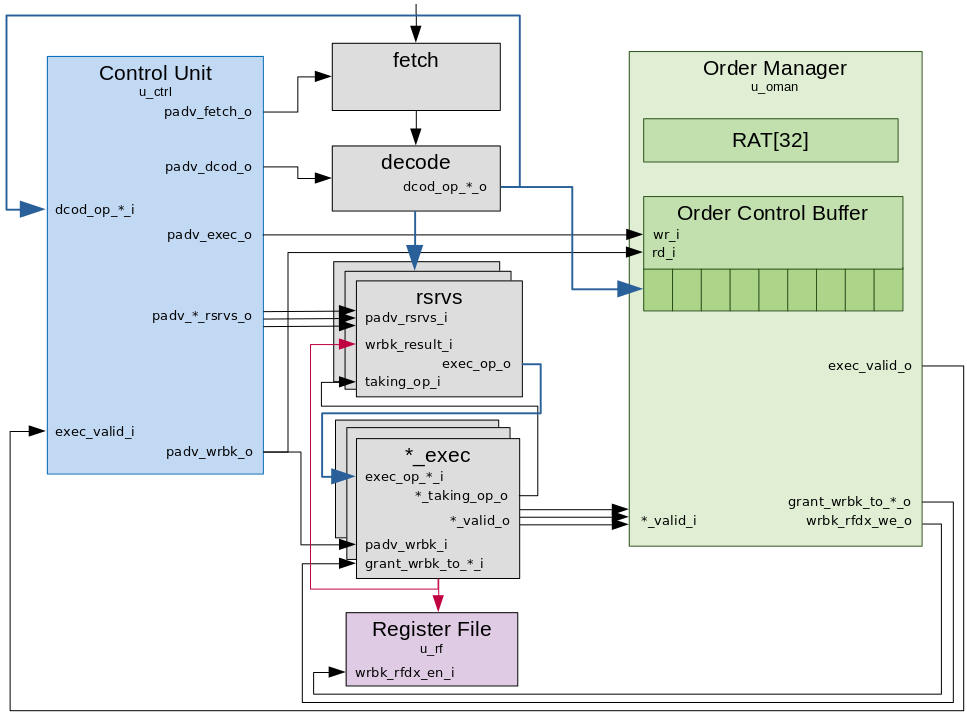
A simplified view of the CPU’s internal module layout is as per the below diagram.

Pipeline Controls
The marocchino has two modules for coordinating pipeline stage instruction propagation. The control unit and the order manager.
Control Unit
The control unit of the CPU is in charge of watching over the pipeline stages
and signalling when operations can transfer from one stage to the next. The
Marocchino does this with a series of pipeline advance (padv_*) signals. In
general for the best efficiency all padv_* wires should be high at all times
allowing instructions to progress on every clock cycle. But as we will see in
reality, this is difficult to achieve due to pipeline stall scenarios like cache
misses and branch prediction misses. The padv_* signals include:
padv_fetch_o
The padv_fetch_o signal instructs the instruction fetch unit to progress.
Internally the fetch unit has 3 stages. The instruction fetch unit interacts
with the instruction cache and instruction memory management unit (MMU).
The padv_fetch_o signal goes low and the pipeline stalls when the decode
module is busy (dcod_emtpy_i is low). The signal dcod_empty_i comes from
the Decode module and indicates that an instruction can be accepted by the
decode stage.
This is represented by this assign in or1k_marocchino_ctrl.v:
Note The stepping and pstep[] signals are related to debug single stepping, and can be
ignored for our purposes.
  // Advance IFETCH
  // Stepping condition is close to the one for DECODE
  assign padv_fetch_o = padv_all & ((~stepping) | (dcod_empty_i & pstep[0])); // ADV. IFETCH
padv_dcod_o
The padv_dcod_o signal instructs the instruction decode stage to output
decoded operands. The decode unit is one stage, if padv_dcod_o is high, it
will decode the instruction input every cycle.
The padv_dcod_o signal goes low if the destination reservation station for the
operands cannot accept an instruction.
This is represented by this assign in or1k_marocchino_ctrl.v:
  // Advance DECODE
  assign padv_dcod_o = padv_all & (~wrbk_rfdx_we_i) & // ADV. DECODE
    (((~stepping) & dcod_free_i & (dcod_empty_i | ena_dcod)) | // ADV. DECODE
       (stepping  & dcod_empty_i & pstep[0])); // ADV. DECODE
padv_exec_o and padv_*_rsrvs_o
The padv_exec_o signal to order manager enqueues decoded ops into the Order Control
Buffer (OCB). The OCB is a FIFO
queue which keeps track of the order instructions have been decoded.
The padv_*_rsrvs_o signal wired one of the reservation stations
enables registering of an instruction into a reservation station. There is one
padv_*_rsrvs_o signal and reservation station per execution unit. They are:
padv_1clk_rsrvs_o- to the reservation station for single clock ALU operationspadv_muldiv_rsrvs_o- to the reservation station for multiply and divide operations. Divide operations take 32 clock cycles. Multiply operations execute with 2 clock cycles.padv_fpxx_rsrvs_o- to the reservation station for the floating point unit (FPU). There are multiple FPU operations including multiply, divide, add, subtract, comparison and conversion between integer and floating point.padv_lsu_rsrvs_o- to the reservation station for the load store unit. The load store unit will load data from memory to registers or store data from registers to memory. It interacts with the data cache and data MMU.
Both padv_exec_o and padv_*_rsrvs_o are dependent on the execution units being
ready and both signals will go high or low at the same time.
This is represented by the assign in or1k_marocchino_ctrl.v:
  // Advance EXECUTE (push OCB & clean up  DECODE)
  assign padv_exec_o         = ena_exec         & padv_an_exec_unit;
  // Per execution unit (or reservation station) advance
  assign padv_1clk_rsrvs_o   = ena_1clk_rsrvs   & padv_an_exec_unit;
  assign padv_muldiv_rsrvs_o = ena_muldiv_rsrvs & padv_an_exec_unit;
  assign padv_fpxx_rsrvs_o   = ena_fpxx_rsrvs   & padv_an_exec_unit;
  assign padv_lsu_rsrvs_o    = ena_lsu_rsrvs    & padv_an_exec_unit;
padv_wrbk_o
The padv_wrbk_o signal to the execution units will go active when exec_valid_i is active
and will finalize writing back the execution results. The padv_wrbk_o signal to
the order manager will retire the oldest instruction from the OCB.
This is represented by this assign in or1k_marocchino_ctrl.v:
  // Advance Write Back latches
  wire   exec_valid_l = exec_valid_i | op_mXspr_valid;
  assign padv_wrbk_o  = exec_valid_l & padv_all & (~wrbk_rfdx_we_i) & ((~stepping) | pstep[2]);
An astute reader would notice that there are no pipeline advance (padv_*)
signals to each of the execution units. This is where the order manager comes
in.
Order Manager
The order manager ensures that instructions are retired in the same order that they are decoded. It contains a register allocation table (RAT) for hazard resolution and the OCB. We will go into more depth on the RAT in the next article, but for now let’s look at how the order manager interacts with the instruction pipeline flow.
exec_valid_o
As the OCB is a FIFO queue the output port presents the oldest non retired
instruction to the order manager. The exec_valid_o signal to the control unit
will go active when the *_valid_i signal from the execution unit and the OCB
output instruction match.
This is represented by this assign in or1k_marocchino_oman.v:
  assign exec_valid_o =
    (op_1clk_valid_l          & ~ocbo[OCBTC_JUMP_OR_BRANCH_POS]) | // EXEC VALID: but wait attributes for l.jal/ljalr
    (exec_jb_attr_valid       &  ocbo[OCBTC_JUMP_OR_BRANCH_POS]) | // EXEC VALID
    (div_valid_i              &  ocbo[OCBTC_OP_DIV_POS])         | // EXEC VALID
    (mul_valid_i              &  ocbo[OCBTC_OP_MUL_POS])         | // EXEC VALID
    (fpxx_arith_valid_i       &  ocbo[OCBTC_OP_FPXX_ARITH_POS])  | // EXEC VALID
    (fpxx_cmp_valid_i         &  ocbo[OCBTC_OP_FPXX_CMP_POS])    | // EXEC VALID
    (lsu_valid_i              &  ocbo[OCBTC_OP_LS_POS])          | // EXEC VALID
                                 ocbo[OCBTC_OP_PUSH_WRBK_POS];     // EXEC VALID
The OCB helps the order manager ensure that instructions are retired in the same order that they are decoded.
grant_wrbk_*_o
The grant_wrbk_*_o signal to the execution units will go active depending on
the OCB output port instruction.
This is represented by this assign in
or1k_marocchino_oman.v:
  // Grant Write-Back-access to units
  assign grant_wrbk_to_1clk_o        = ocbo[OCBTC_OP_1CLK_POS];
  assign grant_wrbk_to_div_o         = ocbo[OCBTC_OP_DIV_POS];
  assign grant_wrbk_to_mul_o         = ocbo[OCBTC_OP_MUL_POS];
  assign grant_wrbk_to_fpxx_arith_o  = ocbo[OCBTC_OP_FPXX_ARITH_POS];
  assign grant_wrbk_to_lsu_o         = ocbo[OCBTC_OP_LS_POS];
  assign grant_wrbk_to_fpxx_cmp_o    = ocbo[OCBTC_OP_FPXX_CMP_POS];
The grant_wrbk_*_o signal along with the padb_wrbk_o signal signal an
execution unit that it can write back its result to the register file / RAT /
reservation station.
wrbk_rfd1_we_o, wrbk_rfd2_we_o and wrbk_rfdx_we_o
The wrbk_rfd1_we_o and wrbk_rfd2_we_o signals enable writeback
to the register file. There are 2 signals because some 64-bit FPU instructions
require writing results to 2 registers. When there is just a single register to write
only signal wrbk_rfd1_we_o is used. When there are two results, writing happens
in 2-stages, first wrbk_rfd1_we_o signals the write back to register 1 then in
the next cycle wrbk_rfd2_we_o signals the write back to register 2.
The wrbk_rfdx_we_o signal to the control unit stalls the pipeline to allow
the second write to complete.
This is represented by this logic in or1k_marocchino_oman.v:
  // instuction requests write-back
  wire exec_rfd1_we = ocbo[OCBTA_RFD1_WRBK_POS];
  wire exec_rfd2_we = ocbo[OCBTA_RFD2_WRBK_POS];

...

  // 1-clock Write-Back-pulses
  //  # for D1
  always @(posedge cpu_clk) begin
    if (padv_wrbk_i)
      wrbk_rfd1_we_o <= exec_rfd1_we;
    else
      wrbk_rfd1_we_o <= 1'b0;
  end // @clock

  //  # for D2 we delay WriteBack for 1-clock
  //    to split write into RF from D1
  always @(posedge cpu_clk) begin
    if (cpu_rst) begin
      wrbk_rfdx_we_o <= 1'b0; // flush
      wrbk_rfd2_we_o <= 1'b0; // flush
    end
    else if (wrbk_rfd2_we_o) begin
      wrbk_rfdx_we_o <= 1'b0; // D2 write done
      wrbk_rfd2_we_o <= 1'b0; // D2 write done
    end
    else if (wrbk_rfdx_we_o)
      wrbk_rfd2_we_o <= 1'b1; // do D2 write
    else if (padv_wrbk_i)
      wrbk_rfdx_we_o <= exec_rfd2_we;
  end // @clock
The padv_wrbk_i signal from the control unit to the order manager also takes
care of dequeuing the last instruction from the OCB. With that and the
writebacks completed the instruction is said to be retired.
Conclusion
The Marocchino instruction pipeline is not very complicated while still being full featured including Caches, MMU and FPU. We have mentioned a few structures such as Reservation Station and RAT which we haven’t gone into much details on. These help implement out-of-order superscalar execution using Tomasulo’s algorithm. In the next article we will go into more details on these components and how Tomasulo works.