This is an ongoing series of posts on the Marocchino CPU, an open source out-of-order OpenRISC cpu. In this series we are reviewing the Marocchino and it’s architecture. If you haven’t already I suggest you start of by reading the intro in Marocchino in Action.
In the last article, Marocchino Instruction Pipeline we discussed the architecture of the CPU. In this article let’s look at how Marocchino achieves out-of-order execution using the Tomasulo algorithm.
Achieving Out-of-Order Execution
In a traditional pipelined CPU the goal is retire one instruction per clock cycle. Any pipeline stall means an execution clock cycle will be lost. One method for reducing the affect of pipeline stalls is instruction parallelization. In 1993 the Intel Pentium processor was one of the first consumer CPUs to achieve this with it’s dual U and V integer pipelines. The pentium U and V pipelines require certain coding techniques to take full advantage. Achieving more parallelism requires more sophisticated data hazard detection and instruction scheduling. Introduced with the IBM System/360 in the 60’s by Robert Tomasulo, the Tomosulo Algorithm provides the building blocks to allow for multiple instruction execution parallelism. Generally speaking no special programming is needed to take advantage of instruction parallelism on a processor implementing Tomasulo algorithm.
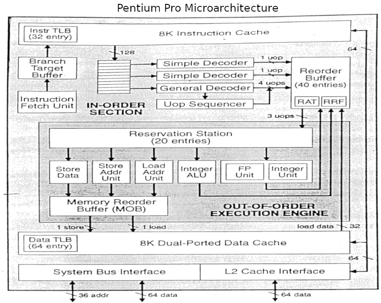
Though the technique of out-of-order CPU execution with Tomasulo’s algorithm had been designed in the 60’s it did not make its way into popular consumer hardware until the Pentium Pro in the 1995. Further Pentium revisions such as the Pentium III, Pentium 4 and Core architectures are based on this same architecture. Understanding this architecture is a key to understanding modern CPUs.
In this article we will point out comparisons between the Marocchino and Pentium pro who’s architecture can be seen in the below diagram.
The Marocchino implements the Tomasulo algorithm in a CPU that can be synthesized and run on an FPGA. Let’s dive into the implementation by breaking down the building blocks used in Tomasulo’s algorithm and how they have been implemented in Marocchino.
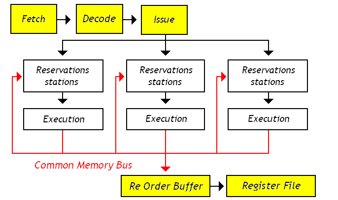
Tomasulo Building blocks
Besides the basic CPU modules like Instruction Fetch, Decode and Register File, the building blocks that are used in the Tomasulo algorithm are as follows:
- Reservation Station - A queue where decoded instructions are placed before they can be executed. Instructions are placed in the queue with their decoded operation and available arguments. If any arguments are not available the reservation station will wait until the arguments are available before executing.
- Execution Units - The execution units include the Arithmetic Logic Unit (ALU), Memory Load/Store Unit or FPU is responsible for performing the instruction operation.
- Re-order Buffer (ROB) - A ring buffer which manages the order in which instructions are retired. In Marocchino the implementation is slightly simplified and called the Order Control Buffer (OCB).
- Instruction Ids - As an instruction is queued into the ROB, or OCB in Marocchino
it is assigned an Instruction Id which is used to track the instruction in different
components in Marocchino code this is called the
extaddr. - Register Allocation Table (RAT) - A table used for data hazard resolution. The RAT table has one cell per OpenRISC general purpose register, 32 entries. Each RAT cell indicates if a register is busy being produced by a queued instruction and which instruction will produce it.
- Common Data Bus - Execution units present their result to all reservation stations along with the register file. Writing to the reservation station provides immediate resolution of data hazards. The link between execution units, reservation stations and register file is referred to as the common data bus.
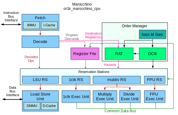
The below diagram shows how these components are arranged in the Marocchino processor.
Resolving Data Hazards
As mentioned above the goal of a pipelined architecture is to retire one instruction per clock cycle. Pipelining helps achieve this by splitting an instruction into pipeline stages i.e. Fetch, Decode, Execute, Load/Store and Register Write Back. If one instruction depends on the results produced by a previous instruction will be a problem as register write back of the previous instruction may not complete before registers are read during the Decode phase of a instruction. This and other types of dependencies between pipeline stages are called hazards, and they must be avoided.
The Tomasulo algorithm with its Reservation Stations, Register Allocation Tables and other building blocks try to avoid hazards causing pipeline stalls. Let’s look at a simple example to see how this is done.
- instruction 1 -
b = a * 2 - instruction 2 -
x = a + b - instruction 3 -
y = x / y
Here we can see that instruction 2 depends on instruction 1 as the addition
of a + b cannot be performed until b is produced by instruction 1.
Let’s assume that instruction 1 is currently executing on the MULTIPLY unit.
The CPU decodes instruction 2, instead of detecting a data hazard and stalling
the pipeline instruction 2 will be placed in the reservation station of the
ADD execution unit. The RAT indicates that b is busy and being produced by
insruction 1. This means instruction 2 cannot execute right away. Next, we
can look at instruction 3 and place it onto the reservation station of the
DIVIDE execution unit. As instruction 3 has no hazards for x and y it
can proceed directly to execution, even before instruction 2 is ready for
execution.
Note, if a required reservation station is full the pipeline will stall.
Register Renaming
As mentioned above, execution units will present their output onto the common
data bus wrbk_result and the data will be written into reservation stations.
Writing the register to the reservation station may occur before writing
back to the register file. This is what register renaming is, as the
register input does not come directly from the register file.
Instruction Id
When an instruction is issued it may be registered in the RAT, OCB and Reservation
Station. It is assigned an Instruction Id for tracking purposes. In Marocchino
this is called the extadr and is 3 bits wide. It is generated by the simple
instruction ID generation logic.
The is implemented in or1k_marocchino_oman.v with the following counter
logic which generates a new extadr every time an instruction is decoded.
  // extension to DEST, FLAG or CARRY
  // Zero value is reserved as "not used"
  localparam [DEST_EXTADR_WIDTH-1:0] EXTADR_MAX = ((1 << DEST_EXTADR_WIDTH) - 1);
  localparam [DEST_EXTADR_WIDTH-1:0] EXTADR_MIN = 1;
  // ---
  reg  [DEST_EXTADR_WIDTH-1:0] dcod_extadr_r;
  wire [DEST_EXTADR_WIDTH-1:0] extadr_adder;
  // ---
  assign extadr_adder = (dcod_extadr_r == EXTADR_MAX) ? EXTADR_MIN : (dcod_extadr_r + 1'b1);
  // ---
  always @(posedge cpu_clk) begin
    if (pipeline_flush_i)
      dcod_extadr_r <= {DEST_EXTADR_WIDTH{1'b0}};
    else if (padv_dcod_i)
      dcod_extadr_r <= fetch_valid_i ? extadr_adder : dcod_extadr_r;
  end // @clock
  // support in-1clk-unit forwarding
  assign dcod_extadr_o = dcod_extadr_r;
Every instruction that is queued by the order manager is designated
an extadr. This allows components like the reservation station and RAT tables
to track when an instruction starts and completes executing.
The interactions between the extadr and other components are as follows.
During decode:
- the ID generator generates the
extaddrby incrementing a counter. - the OCB registers the
extaddralong with other decoded instruction details - the RAT registers an
extaddrfor the decoded instruction to indicate which instruction will resolve a hazard.
During execution:
- the OCB broadcasts the
extaddrof the oldest instruction registered in a FIFO fashion. This is to indicate which instruction is to be retired and ensures instructions are retired in order. - the RAT outputs the
extaddrindicating which queued instruction will produce a register - the RAT receives an
extaddrfrom the OCB output to clear allocation flags - the Reservation Station receives the
extaddrwith hazards to track when instructions have finished and results are available.
Register Allocation Table
The register allocation table (RAT), sometimes called register alias table, keeps track of which registers are currently in progress of being generated by pending instructions. This is used to derive and resolve hazards.
The outputs of the RAT cell are:
rat_rd_extadr_o- indicates whichextadrinstruction has been allocated to generate this register. This will be updated withdecod_extadr_iwhenpadv_exec_igoes high.rat_rd_alloc_o- indicates that this register is currently allocated to an instruction which is not yet complete. This will be set whenpadv_exec_igoes high,decod_rfd_we_iis high, anddcod_rfd_adr_iis equal toGPR_ADR.
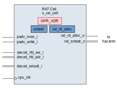
The RAT table is made of 32 rat_cell modules; one cell per register. The
register which the cell is allocated to is stored within GPR_ADR in the rat
cell.
Outputs of the RAT are registered to reservation stations. The hazards are derived with the following logic in or1k_marocchino_oman.v.
The omn2dec_hazard_d1a1_o hazard means that the argument a of the decoded
instruction will be resolved when the instruction with extadr in omn2dec_extadr_dxa1_o is
retired. The 2 in d2, a2 and b2 represent the 2nd register used in 64-bit
FPU instructions.
  //  # relative operand A1
  assign omn2dec_hazard_d1a1_o = rat_rd1_alloc[dcod_rfa1_adr_i] & dcod_rfa1_req_i;
  assign omn2dec_hazard_d2a1_o = rat_rd2_alloc[dcod_rfa1_adr_i] & dcod_rfa1_req_i;
  assign omn2dec_extadr_dxa1_o = rat_extadr[dcod_rfa1_adr_i];
  //  # relative operand B1
  assign omn2dec_hazard_d1b1_o = rat_rd1_alloc[dcod_rfb1_adr_i] & dcod_rfb1_req_i;
  assign omn2dec_hazard_d2b1_o = rat_rd2_alloc[dcod_rfb1_adr_i] & dcod_rfb1_req_i;
  assign omn2dec_extadr_dxb1_o = rat_extadr[dcod_rfb1_adr_i];
  //  # relative operand A2
  assign omn2dec_hazard_d1a2_o = rat_rd1_alloc[dcod_rfa2_adr_i] & dcod_rfa2_req_i;
  assign omn2dec_hazard_d2a2_o = rat_rd2_alloc[dcod_rfa2_adr_i] & dcod_rfa2_req_i;
  assign omn2dec_extadr_dxa2_o = rat_extadr[dcod_rfa2_adr_i];
  //  # relative operand B2
  assign omn2dec_hazard_d1b2_o = rat_rd1_alloc[dcod_rfb2_adr_i] & dcod_rfb2_req_i;
  assign omn2dec_hazard_d2b2_o = rat_rd2_alloc[dcod_rfb2_adr_i] & dcod_rfb2_req_i;
  assign omn2dec_extadr_dxb2_o = rat_extadr[dcod_rfb2_adr_i];
Reservation Stations
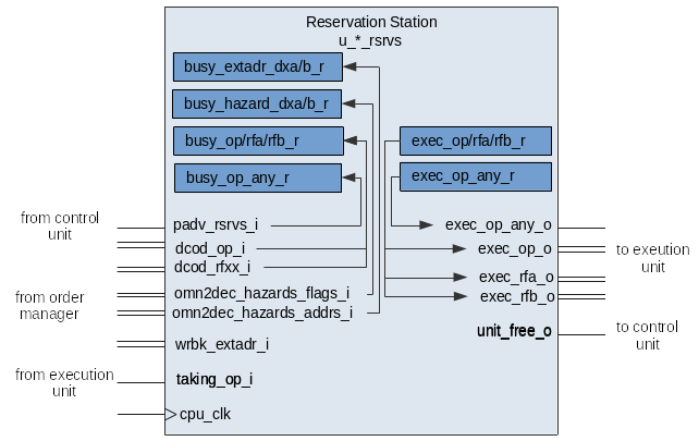
The reservation station receives an instruction from the decode stage and queues it until all hazards are resolved and the execution unit is free.
Each reservation station has one busy slot and one execution slot. In the Pentium Pro there were 20 reservation station slots, the Marocchino has 5 or 10 depending if you count the execution slots.
Reservation stations are populated when the pipeline advance padv_rsrvs_i signal comes.
An instruction may be forwarded directly to execution if there are no hazards
and the execution unit is free.
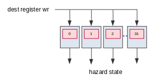
busy_extadr_dxa_r- is populated with data fromomn2dec_hazards_addrs_i. Thebusy_extadr_dxa_rregister represents theextadrto look for which will resolve the A register hazard.-
busy_extadr_dxb_r- same as ‘A’ but indicates whichextadrwill produce the B register. busy_hazard_dxa_r- is populated with data fromomn2dec_hazards_flags_i. Thebusy_hazard_dxa_rregister represents that there is an instruction executing that will produce register A which has not yet completed.-
busy_hazard_dxb_r- same as ‘A’ but indicates that ‘B’ is not available yet. busy_op_any_r- populated with1whenpadv_rsrvs_igoes high indicates that there is an operation queued.busy_op_r- populated withdcod_op_i. Represents the operation pending in the queue.busy_rfa_r- populated with data fromdcod_rfxx_i. Represents the value of operand A pending in the queue.busy_rfb_r- populated with data fromdcod_rfxx_i. Represents the value of operand B pending in the queue.
The reservation station resolves hazards by watching and comparing wrbk_extadr_i
with the busy_extadr_dxa_r and busy_extadr_dxb_r registers. If the two match
it means that the instruction producing register A or B has finished writing back
its results and the hazard can be cleared.
Writeback forwarding is handled via the following verilog multiplexer and register logic.
The first bit is used to register the decoded values dcod_rf* from the register
file otherwise we watch for inputs from the forwarding logic. If there is a pending hazard
results are forwarded from the common data bus, otherwise results are maintained.
  // BUSY stage operands A1 & B1
  always @(posedge cpu_clk) begin
    if (padv_rsrvs_i) begin
      busy_rfa1_r <= dcod_rfa1;
      busy_rfb1_r <= dcod_rfb1;
    end
    else begin
      busy_rfa1_r <= busy_rfa1;
      busy_rfb1_r <= busy_rfb1;
    end
  end // @clock

  // Forwarding
  //  operand A1
  assign busy_rfa1 =  busy_hazard_d1a1_r ? wrbk_result1_i :
                     (busy_hazard_d2a1_r ? wrbk_result2_i : busy_rfa1_r);
  //  operand B1
  assign busy_rfb1 =  busy_hazard_d1b1_r ? wrbk_result1_i :
                     (busy_hazard_d2b1_r ? wrbk_result2_i : busy_rfb1_r);
When all hazard flags are cleared the contents of busy_op_r , busy_rfa_r and
busy_rfb_r will be transferred to exec_op_any_r, exec_op_r, etc. They
are presented on the outputs and the execution unit can take them and start processing.
The unit_free_o output signals the control unit that the reservation station
is free and can be issued another instruction. The signal goes high when all hazards
are cleared and the busy state transfers to exec.
Execution Units
In Marocchino the execution units (also referred to as functional units) execute instructions which it receives from the reservation stations.
The execution units in Marocchino are:
or1k_marocchino_int_1clk- handles integer instructions which can complete in 1 clock cycle. This includesSHIFT,ADD,AND,ORetc.or1k_marocchino_int_div- handles integerDIVIDEoperations.or1k_marocchino_int_mul- handles integerMULTIPLYoperations.or1k_marocchino_lsu- handles memory load store operations. It interfaces with the data cache, MMU and memory bus.pfpu_marocchino_top- handles floating point operations. These includeADD,MULTIPLY,CMP,I2Fetc.
Handshake signals between the reservation station and execution units are used to issue operations to execution units.
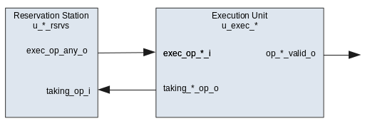
The taking_op_i is the signal from the execution unit signalling it has
received the op and the reservation station will clear all exec_*_o output
signals.
Order Control Buffer
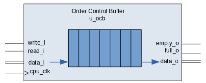
In the Marocchino the Order Control Buffer (OCB) is the in order retirement unit. It can retire a single instruction at a time. The implementation is a 7 entry FIFO queue. This is much less than the Pentium Pro which contains 40 slots. The OCB receives a single instruction at time from the decoder and broadcasts the oldest instruction for other components to see. Instructions are retired after execution write back is complete.
If the OCB output indicates a branch instruction or an exception, branch logic is invoked. Instead of waiting for write back to a register the write back logic in the Marocchino will perform the branch operations. This may include flushing the OCB. Special care is taken to handle branch delay slot instruction execution.
The OCB is different from a traditional Tomasulo Reorder Buffer (ROB) in that it does not store any execution write back results.
Each OCB entry stores:
- The Instruction ID
extaddr - The type of instruction
- The register destination addresses used for write back
- Any Fetch and Decode exceptions
This can be seen as defined by the ocbi and ocbi wire buses in
or1k_marocchino_oman.v.
  // --- OCB-Controls input ---
  wire  [OCBT_MSB:0] ocbi;
  assign ocbi =
    {
      // --- pipeline [C]ontrol flags ---
      dcod_extadr_r, // OCB-Controls entrance
      dcod_op_ls_i, // OCB-Controls entrance
      dcod_op_fpxx_cmp_i, // OCB-Controls entrance
      dcod_op_fpxx_arith_i, // OCB-Controls entrance
      dcod_op_mul_i, // OCB-Controls entrance
      dcod_op_div_i, // OCB-Controls entrance
      dcod_op_1clk_i, // OCB-Controls entrance
      dcod_op_jb_r, // OCB-Controls entrance
      dcod_op_push_wrbk_i, // OCB-Controls entrance
      // --- instruction [A]ttributes ---
      pc_decode_i, // OCB-Attributes entrance
      dcod_rfd2_adr_i, // OCB-Attributes entrance
      dcod_rfd2_we_i, // OCB-Attributes entrance
      dcod_rfd1_adr_i, // OCB-Attributes entrance
      dcod_rfd1_we_i, // OCB-Attributes entrance
      dcod_delay_slot_i, // OCB-Attributes entrance
      dcod_op_rfe_i, // OCB-Attributes entrance
      // Flag that istruction is restartable
      interrupts_en, // OCB-Attributes entrance
      // Combined IFETCH/DECODE an exception flag
      dcod_an_except_fd_i, // OCB-Attributes entrance
      // FETCH & DECODE exceptions
      dcod_fetch_except_ibus_err_r, // OCB-Attributes entrance
      dcod_fetch_except_ipagefault_r, // OCB-Attributes entrance
      dcod_fetch_except_itlb_miss_r, // OCB-Attributes entrance
      dcod_except_illegal_i, // OCB-Attributes entrance
      dcod_except_syscall_i, // OCB-Attributes entrance
      dcod_except_trap_i // OCB-Attributes entrance
    };

  // --- INSN OCB input ---
  wire [OCBT_MSB:0] ocbo;
Common Data Bus
As discussed above the common data collects write back results from execution units and routes them for write back.
This can be seen in the or1k_marocchino_cpu.v as below.
  // --- regular ---
  always @(wrbk_1clk_result       or wrbk_div_result or wrbk_mul_result or
           wrbk_fpxx_arith_res_hi or wrbk_lsu_result or wrbk_mfspr_result)
  begin
    wrbk_result1 = wrbk_1clk_result       | wrbk_div_result | wrbk_mul_result |
                   wrbk_fpxx_arith_res_hi | wrbk_lsu_result | wrbk_mfspr_result;
  end

  // --- FPU64 extention ---
  assign wrbk_result2 = wrbk_fpxx_arith_res_lo;
Conclusion
Tomasulo’s algorithm is still relevant today and used in many processors. Marocchino provides an accessible implementation. Marocchino is however, not super-scalar, while Pentium Pro can decode up to 4 instructions at a time the Marocchino can only decode 1 at a time.
Furthermore many improvements can be made to Marocchino to increase performance. Including:
- Full featured reorder buffer
- Parallel instruction decoding
- Speculative execution; or should we?
- More reservation station slots
However, these come with a cost of size on the FPGA. If you are interested in helping out please feel free to contribute.
If anything in this article could be improved, more timing diagrams, typos or fixes for diagrams please send me a message on twitter.
Further Reading and Sources
- Intel architecture manuals
- Intel Architecture Software Developers Manual PDF see
- section 2.1 brief history of the intel architecture
- section 2.4 introduction to the P6 microarchitecture
- Pentium Pro Datasheet PDF see
- section 2.2 The Pentium Pro Processor Pipeline
- Intel Architecture Software Developers Manual PDF see
- University of Washington, Computer Architecture
- Re-order buffer - source of Pentium Pro diagram
- UCSD, Graduate Computer Architecture
- Intel Core 2
- Intel Pentium Pro